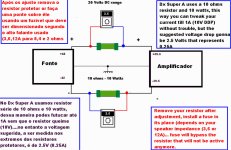
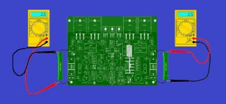
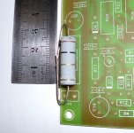
Here you have the adjustment setup
You may have this protective series resistor on board, or maybe not...we are still thinking about it, as people may burn the fiberglass with some kind of misadjustment or errors into the circuit board assembly... fuse socket is to be installed on board..but resistor may be outside, in between the supply pcboard and the power amplifier pcboard.... installed to adjust and them removed.
Image attached,
regards,
Carlos
Attachments
Last edited:
This resistor watt rate is an overkill
2.5 volts over 10 ohms, means 250mA and this result in 625mW
But 5.0 volts means 500mA and this result in 2.5W
If people try 700mA, then the voltage drop will b 7 volts... results in 5W
But if people make mistakes into the amplifier constrution, shorts and things alike, misadjustment into the bias trimpot..them the current can be several amperes and even the 10 watts resistor will smoke.
This watt ratio will be good to the tweakers...for sure they gonna try 1 Ampere, they will regret and will return to 0.25A
The VBE multiplier working as heat sensor is unable to compensate when the heatsink is too much hot.... so.... with huge dissipation of 60 watts each rail or more, the heatsink will be so hot the transistor will not be able to reduce in the ammount we need....this way...or you use small current or you install dual super fan blowers and giant heatsink and install this devil machine (hot) over a block of Ice in Siberia or Sweden.
Big mistakes will smoke protective resistors anyway...well....they are there for this reason.... to avoid excessive current into the circuit board and to burn opening the circuit alike a fusistor.
regards,
Carlos
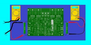
Your left multimeter will not read...because no black cable
The one at post 304 is defective.
Ohohohohohôh!🙂
regards,
Carlos
The one at post 304 is defective.
Ohohohohohôh!🙂
regards,
Carlos
Attachments
Last edited:
Mucho loco gracias a Dios!... very crazy thanks God
If i was not crazy, how could i tollerate some guys we have around in our forum (10 guys)
If i was not crazy i would not take all my free time to create, develop, build, design, test and torture amplifiers.
If i was not crazy no way to help layout designers to follow "Corporation" rules.
If i was not crazy no tenths of amplifier produced for free.
If not crazy 1000 guys would not have the pleasure to make their own audio power amplifier... with their own hands...in their own house.
Thanks God uncle charlie is idiot, and crazy!
regards,
Carlos
Member
Joined 2009
Paid Member
Thank you Bigun...you are a friend... reason why you use to give
me some "discount" in your evaluations.
This is the final comment about the Dx Super A.... adjustment and how the circuit goes operating...thermal issues, thermal drift, what we can do..what we cannot do.
I hope you enjoy
Dx Super A adjustment - YouTube
Please subscribe to Carlos Mergulhão in the Youtube..this helps me to attract more guys to build my amplifiers..the more subscribers the more guys comes to see my videos...please click into like, the fingers up image...and leave a comment if you want.
Sorry, i have heard and i could see my english is not good....but it is the best i can do.
regards,
Carlos
Humans are lovely
Creativity and ingenuity... these thingas applied to audio electronics will bring wonders to our lives.
regards,
Carlos
Creativity and ingenuity... these thingas applied to audio electronics will bring wonders to our lives.
regards,
Carlos
Attachments
-
 481318134.jpg47 KB · Views: 192
 -
 485839045.jpg40.2 KB · Views: 191
 -
 4853565810.jpg19.9 KB · Views: 207
 -
 487804232.jpg23.3 KB · Views: 199
 -
 4822398911.jpg21.2 KB · Views: 184
 -
 486921119.jpg28.8 KB · Views: 184
 -
 483237107.jpg65.8 KB · Views: 197
 -
 4865446712.jpg32.1 KB · Views: 184
 -
 482186168.jpg31.5 KB · Views: 182
 -
 483341173.jpg25.2 KB · Views: 238
Dx Super A playing at Bazzo's home in São Paulo
This guy repairs automobile steel parts.... we call here "lanterneiro" or "funileiro", i do not know the name of someone that fixes damage in your car doors, for instance.
teste cabeçote 02 - YouTube!
teste cabeçote 01 - YouTube!
They call power unit as "cabeçote"...that means top of an engine, where the valves are.... where the overhead cam shaft is.... the name came from this analogy.
Brazil is too big, we have several "languages" in our country..also music is very different ... this ones sound strange to me.
http://www.youtube.com/watch?feature=player_embedded&v=DhfqQqeFP4A
Creativity and passion...also a very bad acoustic (ceramic tiles in the floor) and the terrible tone control added to an awfull digital camera resulted more or less.
regards,
Carlos
Last edited:
Good morning Carlão!
The tone control works correctly, with pots to the center of resistance, the frequencies that come out that are the same ...
I did extensive testing before installing, because if I'm not pleased, I throw the trash ... lol
The real problem is the same of sony digital camera, you can not play what I hear ... And what I hear, is simply indescribable!!
Regards ...
Thanks Renato, you are right, these cameras are not good
for audio recording.
Sorry, i hate tone controls...i do like sound directly into the power amplifier input connector...more pure sonics...tone control introduces distortion.
Despite that i have appreciated your videos a lot.
thank you,
regards,
Carlos
for audio recording.
Sorry, i hate tone controls...i do like sound directly into the power amplifier input connector...more pure sonics...tone control introduces distortion.
Despite that i have appreciated your videos a lot.
thank you,
regards,
Carlos
Yes, blame the tone controls become completely unnecessary, since the signal source is clean, which is not often ... So, I implemented this to compensate for bad signal sources, with some deficiency in attendance ...
I tested the controls, the LM 1036 proved very effective, without distorting the perceptual level, unlike other tone controls that do not use CI, but resources for separating frequencies through resistors and capacitors ... I do not like these ...
Hug!

I tested the controls, the LM 1036 proved very effective, without distorting the perceptual level, unlike other tone controls that do not use CI, but resources for separating frequencies through resistors and capacitors ... I do not like these ...
Hug!
Rena,
I don't know what opamp you are using as the unity gain buffer, but do check the datasheet for information on the link from Out to -IN. Some opamps prefer to see a low value resistor in this link, to help prevent misbehaviour.
Check that you have HF decoupling in the correct locations.
I don't know what opamp you are using as the unity gain buffer, but do check the datasheet for information on the link from Out to -IN. Some opamps prefer to see a low value resistor in this link, to help prevent misbehaviour.
Check that you have HF decoupling in the correct locations.
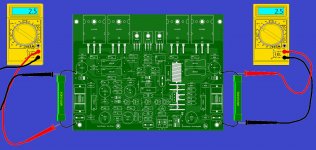
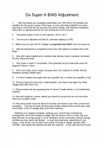
DX is suggesting that some Members/Builders may want to use the fuse alternative resistor to check for amplifier current when using Ibias approaching 1A. Don't do this.
If the PSU is putting out say +-40Vdc when the amplifier is not connected and this drops to +-39.5Vdc when the amplifier is connected then the setting of the bias will further reduce the supply at the amplifier power input terminals slightly, maybe down to +-38Vdc when the bias is set to 100mA to 200mA.
If you insert a 10r resistor instead of the fuse, then the output bias will change from the set value. It might drop to 10mA, but much worse the supply voltage after the resistor will drop badly.
200mA through a 10r resistor will drop 2V.The amplifier will have +-38Vdc at the power terminals but it will only have +-36Vdc after the resistors.
This gets MUCH WORSE if you set the bias to 500mA, Vcc/Vee becomes +-33Vdc,
@ 700mA: +-31Vdc, @ 1A: +-28Vdc
DO NOT SET output bias with resistors replacing the fuses.
The amplifier must see the full supply voltage when you set the output bias.
Use the Vre method to check the output bias current.

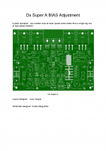
Dx Super A BIAS
Here is a quick instructional information of how to adjust the bias on the Dx Super A. 😀
Regards
Juan
Here is a quick instructional information of how to adjust the bias on the Dx Super A. 😀
Regards
Juan
Attachments
Great Vargas...we are turning into a great team
Long life to the Corporation, the Union of the best world audiophiles..the real DIY folks.
regards,
Carlos
Long life to the Corporation, the Union of the best world audiophiles..the real DIY folks.
regards,
Carlos
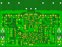
Here are the files for etching hot iron and UV light sensitive boards, there are confusion of if the files is mirrored or no I'm giving you both normal and mirrored files PDF format. 😀 chose the one you need not all printer work the same way.
Regards
Juan
Regards
Juan
Attachments
-
Dx Super A.LAY normal view as your are looking at the bottom of the board inverted.pdf33.1 KB · Views: 393
-
Dx Super A.LAY normal view as your are looking at the bottom of the board.pdf33 KB · Views: 388
-
Dx Super A.LAY normal view as your are looking at the top of the board inverted.pdf33 KB · Views: 337
-
Dx Super A.LAY normal view as your are looking at the top of the board.pdf33 KB · Views: 358
-
 top.png563 KB · Views: 317
 -
 bottom.png509.3 KB · Views: 241
Last edited:
- Home
- Amplifiers
- Solid State
- Dx Blame ST together Dx Super A