Rudi, I would check again to make sure that none of heat sink mounted transistors have shorted to it. As I mentioned earlier, the MJE's I was using both shorted to the heat sink.
You know what damage can occur if you power up under such a condition!
Good luck finding the problem,
Jean
You know what damage can occur if you power up under such a condition!
Good luck finding the problem,
Jean
use a bulb tester at every intermediate stage of construction. It allows safe and damage free power up. Then (while the bulb is glowing and mains power still plugged in) measure where the excessive current is escaping.
They call me "Mr. Bulb", Andrew:
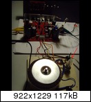
Bild: bulk00398x8.jpg - abload.de
I use a High Voltage Halogen lamp, 40W.
I think, that the problem I am having, is home-made.
I bought a couple of Toshiba KSC5171 and KSA1930 from an ebay-seller (Hongkong) and used them as VAS (KSC5171) and drivers.
I measured the Hfe of a KSC5171 yesterday and my DMM showed a value of 65.
I wonder, if they are counterfeits.
I have already begun to replace them by BD139 and MJE and will power on again - of course with assistance of the bulb tester.
Best regards - Rudi_Ratlos
Dear DX Blame friends,
I really recommend you something like this:
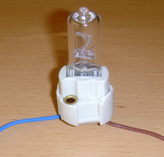
BULB tester
Price: 5€
Function: delimits the output of your transformer to approx. the Watts value of the lamp
Howto: insert the lamp in serial with one of the main's wires of the transformer
Benefit: prevents your precious transformer (and yourself) from "suffering" a short on your AMP PCB
Best regards - Rudi_Ratlos
Hi Rudi, am putting finishing touches on DX ST amp and am using only one transformer. Is it better to run one power supply board for both amp boards or to run two power supply boards, and just conneting the AC inputs of transformers to both power supply boards. Will this make any difference. Appre iate again your effort in making the boards.
Best, John
Best, John
Hello John,
there are 2 ways to do the setup.
First way: 1 transformer and 1 PSU, feeding the power to both of the AMP PCBs, and the second way: 2 transformers and 2 PSUs, each one feeding one AMP PCB.
The first way is more economic, saves space and is - in case the transformer and the reservoir capacitors are big enough - in most cases adequate.
I use the second way - I call it dual-mono setup -, if I feel that the AMP is "worth it".
In this case the power consumption of one channel does not affect the power consumption of the other channel.
According to my ears the DX BlameES with 2 big SANKEN output-transistors was worth a dual-mono setup.
I do not know the DX BlameST, so: it simply depends on your ears and on your feeling.
Best regards - Rudi
Thanks Rudi, I set it up with one transformer and seems to be working nicely on the bias. I had trouble on one channel and fooled around with the trim pot and found that it was broken, replaced it and they both channels bias nicely now. I have 100 R in place of the fuse and adjusted for 10 mv, or should this be 4.7 -6 mvolt as you put in the builders manual. Once I know this then I will cut out the resistors and put in fuses and speakers and try it out.
Cheers, John
Cheers, John
I believe I saw that Carlos adjusted for 10 v with 100 R and 4.7 with 47r over fuses on you tube but not sure which is correct or if it matters too much. However I want to make sure it does not go up in smoke b y too much and am only self taught in these things. thanks again, John
The output bias and the VAS bias and the LTP bias can all change with changes in supply voltage.
If one tries to set up the output bias via a rail dropping protective resistor, then one must recheck the biases of all stages after removing the protective resistor.
If necessary one must properly bias the stages with the normal Rail voltage applied.
BTW,
some amplifiers go way out of acceptable bias current tolerance when the mains voltage changes.
John,
do it as Andrew said.
Remove the resistors across the fuseholders and insert the fuses.
Since you know that your AMP is running, you do not need this resistor any more and you avoid the voltage that drops over this resistor.
Do not connect a speaker to the AMP; short the INPUT (INPUT + = INPUT -).
Switch on the PSU and measure the voltage that drops across the emitter-resistors (0R22).
Depending on the type of output-transistors that you use and the size of your heatsink, adjust the quiescent current so that about 60 - 70mA flows through an emitter resistor, resulting in a voltage drop of about 13 - 15mV over an emitter resistor.
The huge MJL4xxxx transistors can (should) be adjusted to nearly 70mA, a smaller transistor (f.e. NJW0xxx) to 60mA, but this is only my listening impression.
Best regards - Rudi
WOW!
 wow!.... I haven't seen this pictures looks great the red board is amazing man congratulations Rudi on your nice build bro! " me gusta mucho" "I like it a lot"
Regards
vargasmongo3435
wow!.... I haven't seen this pictures looks great the red board is amazing man congratulations Rudi on your nice build bro! " me gusta mucho" "I like it a lot" Regards
vargasmongo3435
Last edited:
- Status
- Not open for further replies.
- Home
- Group Buys
- DX Blame Group Buy