This one is a very good transistor.
no problems i think...to be sure..only installing and testing... i cannot do that because i have not this one here....i suppose you will not face problems with it.
regards,
Carlos
no problems i think...to be sure..only installing and testing... i cannot do that because i have not this one here....i suppose you will not face problems with it.
regards,
Carlos
Be sure the leads position are the same as we have to the BC546/556.
Download both datasheets...the BC datasheet and your MPS datasheet and compare the lead's position...sometimes they are different...not to insert wrong way into the schematic.
If you face oscilations we can fix including some small condensers... i hope this will not be needed.
You have 2N5551/5401, i could not try it as i have not them here anymore..the ones i have are installed in the Troyan/Fokker.
I would like, if possible, you to use the Dx Blame ST, the buider's thread...as i would like to empty this one...not to use this one will be a very good idea, as this one faced a lot of troubles... and the other was made for builders... and this is exactly what you are now a days...a builder.
The link, down this page,the signature (very usefull) will direct you to the thread... you are invited to be there with me during your lovely adventure in the direction of the sonic paradise.
Prepare yourself to strong emotions, the amplifier is awsome and you will experience many pleasant days listening, once again, your recordings and discovering things never perceived before.
Satisfaction is guaranteed!
Tested..super tested...many times tested.... in use for monthes..playing in several homes around our world..inspected in the scope.... simulated several times...if something strange happens..for sure human mistakes (very normal, happens daily with everybody) that you should search..inverted parts, missed parts, wrong values in resistances..these things.... i use to work hard.... round the clock..full time if needed, to be absolutelly sure you have something reliable..this one gave me hard job and hard times...but the result paid me all sweat and tears, the worries and fears.
regards,
Carlos
Last edited:
My Blame-ST is up & running
I need a mono-amplifier to power my twenty-years old Magnat speaker in my study and I don't want to spend too much money.
Looking thru my parts bin, I found that I have most of parts for BlameST. I modified Zharmo's layout so that I can fit the monster DC blocking capacitor (C1).
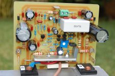
The BlameST sounds very good and it is smooth & relaxing. The amp is quiet (no hum, no hiss) and the DC offset is 15mV. I made the following changes because I have these parts in my parts bin:
C1 : 10uF Evox film capacitor
C20, C22 : 1000uF, 63V
C14, C16, C10(bootstrap) : 100uF, 63V
C18: 270nF polyester capacitor (mounted under the board).
R32: replaced by a link
- Stanley
I need a mono-amplifier to power my twenty-years old Magnat speaker in my study and I don't want to spend too much money.
Looking thru my parts bin, I found that I have most of parts for BlameST. I modified Zharmo's layout so that I can fit the monster DC blocking capacitor (C1).
The BlameST sounds very good and it is smooth & relaxing. The amp is quiet (no hum, no hiss) and the DC offset is 15mV. I made the following changes because I have these parts in my parts bin:
C1 : 10uF Evox film capacitor
C20, C22 : 1000uF, 63V
C14, C16, C10(bootstrap) : 100uF, 63V
C18: 270nF polyester capacitor (mounted under the board).
R32: replaced by a link
- Stanley
Attachments
I am glad you have built and that you have appreciate the unit
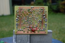
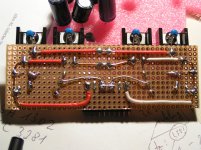
You made a lovely construction...very nice..good pictures....nice soldering below the board...nice clean board....beautifull transformer.
I would like you to publish something...a short review about in the Dx Blame ST - Builder's thread.
I will put your pictures there..modified to be "different", not to post same thing again...please..go there when you find time and say what you have perceived as good and bad...the trimpot position (bias) seems no good.
You have the link down my posts..will send you to the thread.
Thank you very much by your preference, by the pictures and the confidence.
How this amplifier behave with your speaker...felt something good?... felt something bad?
regards,
Carlos
the trimpot position (bias) seems no good.
regards,
Carlos
The space for trimpot is a bit tight and I should have solder the trimpot first. I have got only 200R trimpot and I test the bias with fixed resistor before I solder the trimpot.
I like clean PCB. I used a blunt exacto knife to scrap off the solder flux, then I use toothpaste (which contain mild polishes) & old tooth brush to clean the reminding flux. I then wash the whole board under running water and that is why I prefer to solder the trimpot last. It seems to work quite well as I have been doing this for a few years.
- Stanley
Sorry, my mistake..i was talking about the official Todd Johnson layout
You have made Zharmo layout..... the official one has not too much space to the bias trimpot.
A matter of coincidence you had the same trouble.
regards,
Carlos
You have made Zharmo layout..... the official one has not too much space to the bias trimpot.
A matter of coincidence you had the same trouble.
regards,
Carlos
Carlos, when I look at the schematic of the Blame ES 1.5 you see that R19 is 2K en R20 is 470 Ohm.But when you look at the PCB layout they are switched.
I suppose that the schematic is right or not?
I suppose that the schematic is right or not?
Yes... was a mistake... but when you search for a resistance you search for
the value...you will search for 2K as you will not find resistance any printed with R19 or R20.... reason why nobody failed building....you will find a 2K and will place in the position 2K is indicated..invertion is only in the R19/R20 label, not only the schematic is correct, but also the layout is correct....mistake was the label only.
You should correct in your copy, then no doubt will remain.
This amplifier has not gerbers, so, no way to order boards with silk screen printed on it... this may not be a trouble.
Todd Johnson resigned to produce schematics to the Dx Corporation..he has not free time anymore because his family responsabilities..so...this will not be fixed.
I have to thank Todd Johnson by all his effort allong these last years, but the wonderfull job he has done... Dx Corporation have lost an arm because he resigned... the Corporation's quality will never be matched once again
It is a very sad day to me.... i was perceiving, a long time before, he was already upset by his responsabilities... i was expecting this to happens one day... this was the day.
The ones dislike the Corporation, should organize a party, from now on the quality of my job will be reduced.
Meanman, please, go to the builder's thread for now on, the link is down my posts in the signature position
Carlos
Attachments

Last edited:
Sadly, the Dx Corporation has not layout and schematic designer
To the amplifier Fokker and in special the Troyan (a Fokker using V/I limiter and operating with 100 volts supplies) these ones have not decent layout..i can prepare in an hour using livewire and pcbWizzard..but really...will not result very good.
Troyan will be released July, 17..... for a while, Dx Corporation Greece is taking care of that, Sakis will produce a prototype board that gonna be tested.
Another one used to produce layout for huge power units is Alex MM...but i have no news from him a long time.
regards,
Carlos
It is good..to go checking..but better to do that in the board assembled
will be even better.... the way you have done help people not to feel confused watching the wrong part number...but watching your board you will guarantee your board will operate since the first moment you switch power on.
thank you...was kind to inform that..i cannot fix...we have no more Todd Johnson.
Please... visit the builder's thread and produce some movement there..the link is down the page..in the signature line.
This comment you have made interests the builder's thread.
regards,
Carlos
Last edited:
Moin Volker,
beautiful work - as usual!
I have also made a re-design of my "big-as-a-whale" PCB and could shrink it to 120 x 160 mm - no more "big as a whale",
but only "small as a herring" !
The change: I will no longer solder 2-4 power PSU-caps per rail but only one - say: one 12.000 - 15.000µF cap.
I know the ever-lasting discussion concerning how many caps to use.
I do not like to discuss here.
I would like to have a very compact design of the BlameES, something like this:
Guess what it is?
Best regards - Rudi_Ratlos
beautiful work - as usual!
I have also made a re-design of my "big-as-a-whale" PCB and could shrink it to 120 x 160 mm - no more "big as a whale",
but only "small as a herring" !
An externally hosted image should be here but it was not working when we last tested it.
The change: I will no longer solder 2-4 power PSU-caps per rail but only one - say: one 12.000 - 15.000µF cap.
I know the ever-lasting discussion concerning how many caps to use.
I do not like to discuss here.
I would like to have a very compact design of the BlameES, something like this:
An externally hosted image should be here but it was not working when we last tested it.
Guess what it is?
Best regards - Rudi_Ratlos
An externally hosted image should be here but it was not working when we last tested it.
I don't know, but i like it......nice construction...strong!
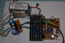
Volker supply is very nice too... very masculine...no decorations...just symetrical and clean..... gut!...zier gut"!
regards,
Carlos
Volker supply is very nice too... very masculine...no decorations...just symetrical and clean..... gut!...zier gut"!
regards,
Carlos
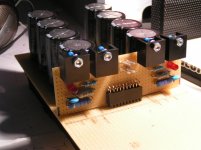
Condensers....how big they should be..... i tried book's instructions
and there i was informed that we need 5000uf to each ampere.
The Dx Amplifier and the Dx Blame ST, or amplifiers powered using 35 volts supplies, sucks 2.5 amperes to each rail and to each channel...so....one supply to each channel should have 12.500uf or up to each rail.
If a single supply is used to feed two channels, then 25.000uf plus 25.000uf gonna be needed.
I have tested...when we have smaller capacitances in the supply, and the amplifier is reproducing non audible tones, alike 8 hertz for instance.... then you should not hear any mains noise (60 or 50 hertz or harmonic) when you amplifier will be putting out the nominal power (100 watts at 4 ohms, sinus input, unclipped).... the tone reproduced is not audible...only some mechanicall noises can be heard from the speaker movement if the speaker is bad..... if you listen mains frequency, then the condensers are not big enougth...i have tried and tested...and book's advice about that is correct.
Watch this video that shows this to you:
http://www.youtube.com/watch?v=KjE_ExOoWWs
regards,
Carlos
Last edited:
Recomended audible "test" for PSRR (fullpower at 8Hz with speaker conected) is very dangerous for conected speaker (bottoming), too big cone displacement .
Audible test was not recommended.... was shown only
the message is:
- "Follow what books says..use 5000uf to each ampere."
I see your english is not very good.... because you misunderstand things, and this is not the first time, so.... your reading is not very good....listening in English seems not very good also.
What about to build something BV, because your comments are usually something we already know..so....this does not help you or us...as a consultant, seems you do not know your audience as you are not leveling your explanations matching the audience knowledge and skills.... alike to tach Albert Einstein to add two numbers....what about to help yourself building some amplifiers..then theories may encounter the reality.
I suggest you to start at Nelson Pass forum...and to build some amplifiers...then, having more experience, building things, you should share something you have learned with us...but build some.... one hundred amplifiers for instance...then we gonna be waiting for your thougths knowing you have the basic skills needed to be a forum teacher.
Another good idea is to read all Solid State forum, this way you will not be repeating things already discussed long time ago..... read all threads and all posts....i have made that three times, post by post...then come to give us more comments, maybe even more usefull than the last one you have made.
regards,
Carlos
Last edited:
🙄Do not worry , Carlos. Is it enough something like this to get right to "touch" You?What about to build something BV
BV Audio P1 Preamplifier, PA300 Power Amplifier home listening test
Is it enouhg? Or newer like this? http://www.bvaudio.sk/PIC/Pic2.jpg
With performance like here SET ?
And yes, english is not my native language, so sorry for mistakes.
Anyway, to do this "test" is not very smart. Place speaker at output, and load supply rails (+ and than -) with power resistor (value for current draw about 2A) ,or light bulb, with input shorted . And You can hear independent +PSSR and -PSSR.
Last edited:
It is good to know Doctor BV.
Take a seat and enjoy this thread..thank you by your presence.
English is not easy for me too.
regards,
Carlos
Take a seat and enjoy this thread..thank you by your presence.
English is not easy for me too.
regards,
Carlos
- Status
- Not open for further replies.
- Home
- Amplifiers
- Solid State
- Dx Blame ES .... based into the Blameless, i am trying a new amplifier