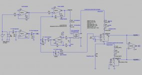
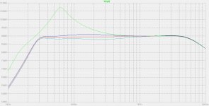
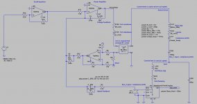
hello, attached you will find a few speed feedback loudspeaker arrangements using a Dual Voice Coil (DVC) speaker driver, with one of the two coils being used as speed sensor. For maximizing the speed feedback, the loudspeaker needs to be current driven. The simulation results look interesting. See attached pictures. Can somebody help me refining the simulations, taking into account the electromagnetic cross-coupling effect of the two coils ? Thanks. Steph. Use the .zip at your will.
Attachments

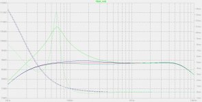
Adding a passive driver may be interesting. The driver excursion becomes lower around the natural resonance frequency.
Attachments
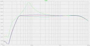
Actually, the results are nice using a damped vented box (bass-reflex). Adding a hole is less costly than adding a passive driver.
Attachments
The dual chamber bandpass is also a possibility, making a subwoofer.
Attachments
Last edited:
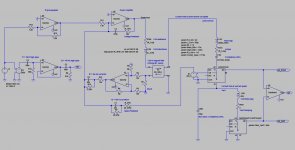
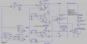
Adding a few circuits using an incremental approach. Taking into account the coils cross-coupling. The cross-coupling has two effects :
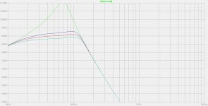
- At a critical frequency equal to roughly 300 Hz, the speed feedback gets counteracted in phase and in amplitude by the coil cross-coupling effect making the system operating in open-loop.
- Above the 300 Hz critical frequency, the coil-cross coupling is dominant in the feedback loop. This induces a closed-loop 1st-order lowpass behaviour above 300 Hz.
Any inductance non-linearity will cause distorsion in the frequency band where the coil-cross coupling dominates the feedback loop. THD could thus increase above 200 Hz or so, when applying coil feedback.
Attachments

Last edited:
- Status
- Not open for further replies.