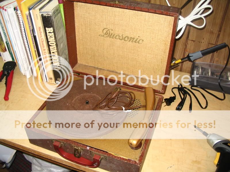
I need either this schematic, or a simular one so that I can recreate this one. I can tell that there is no Power Transformer and the OT is built into the speaker. Any help to direct me to a schematic that will work or even this one would be great.
Patrick
Patrick
You might want to try searching and then asking in the rec.antiques.radio+phono group, at http://groups.google.com .
Good luck.
Good luck.
If that is a pic of the whole amp, it won't take long to figure the schema... what tube is it?
dave
dave
That single (78 RPM) player is somewhat similar to the mult-speed unit I used as a youngster. The circuitry appears to be incomplete. Where's the rectifier?
3 tubes is right, if my childhood recollection is valid. A high O/P (Volts) crystal cart. feeds a voltage amplifier, which (in turn) feeds a power O/P tube. The 3rd tube is the rectifier. Naturally, these things are very low fidelity.
Mounting a 2nd Octal socket is simple enough. Use a CL90 NTC inrush current limiter in series with a UF4007 for rectification. A 12SJ7 and a 50L6 are a reasonable signal tube combo. A 220 Ohm resistor and a 200 Ohm resistor, both rated for 10 W., complete the 150 mA. series heater string.
Crystal carts. go bad over time by absorbing atmospheric moisture. Unless the seals on that old cart. are unusually good, replacement will be necessary. The folks at Garage 'A Records may be able to provide something suitable.
BTW, what type of tube is currently present?
Eli Duttman said:Use a CL90 NTC inrush current limiter in series with a UF4007 for rectification.
And an isolation transformer is highly recommended for safety.
dave
Sam's 19-15 and 19-16 show Duosonic models K-1,2,3, and 4. This is all that is available. Not in Riders or Beitman's.
The rectifier may have been selenium. Year of Sam's pub is 1947. Use a 1N4007 and a resistor. I will post a value if I find a schematic, probably about 200 ohms.
The motor is probably in series with a 25L6GT, so 90V motor. People often replace them with 120V. the motors often run slow and must be disassembled to wash the old smelly green oil out of the bearing felts. All the old dried grease needs to be removed. clean everything with lacquer thinner, varsol won't cut it. be sure and vent the garage well.
The cart is probably a 3V crystal that feeds the grid of the 25L6.
There is no PT, off-line string heater setup.
Replace all the caps for sure, but don't start unless you plan to deal with the dried lubricants.
Don't get one of the original large metal carts with steel needle. Get an Astatic 146 flipunder needle with a real 78 sapphire and a diamond LP. The small tip usually sounds better on a worn 78. Be sure and get one with a red element. They are the later generation sealed in plastic. The others will go bad. ceramics don't go over 1V.
Canadian Astatic may have one, but be sure and get a red element otherwise they are only wrapped in paper.
They are a lot of trouble to rebuild, but they do have a nice sound. Good Luck Mark
Hailteflon
Thank you for the feedback. What I actually want to do is turn this into an old school micro tube amp. I will be removing the motor, I will replace the stylus arm with a Phono jack for a guitar. I want really low volume tube distortion. I will have to take another look a the tube when i get home and i will post that. This thing definently did not ever have another tube in that empty hole though.
You mention Sam's 19-15 and 19-16 as a source for a schematic. Is this a book? I dont have a clue what values of these old caps were.
Patrick
whodatpat said:Hailteflon
Thank you for the feedback. What I actually want to do is turn this into an old school micro tube amp. I will be removing the motor, I will replace the stylus arm with a Phono jack for a guitar. I want really low volume tube distortion. I will have to take another look a the tube when i get home and i will post that. This thing definently did not ever have another tube in that empty hole though.
You mention Sam's 19-15 and 19-16 as a source for a schematic. Is this a book? I dont have a clue what values of these old caps were.
Patrick
Seems like a lot of trouble for a low power guitar amplifier. I'll wager you could build a spud guitar amplifier on an inexpensive hammond chassis with modern tubes, possibly using this speaker and a small surplus power transformer or a couple of 6.3V transformers with one connected in reverse for B+. It will be safer and more easily tweaked.
The current amplifier design probably does not have enough gain for use with a fully passive electric guitar.
kevinkr said:
Seems like a lot of trouble for a low power guitar amplifier. I'll wager you could build a spud guitar amplifier on an inexpensive hammond chassis with modern tubes, possibly using this speaker and a small surplus power transformer or a couple of 6.3V transformers with one connected in reverse for B+. It will be safer and more easily tweaked.
The current amplifier design probably does not have enough gain for use with a fully passive electric guitar.
Alright I am intrigued, what is this spud guitar amp you speak of? Isnt the nedle on a record player just as passive? I want really low volume tube breakup. I am looking for fractional wattage here. Any sugestions are appreciated, but links to schematics are even better. 🙂
Patrick
Don't even think of using that amp for guitar without fitting an isolating transformer
It's dangerous enough in its intended application, but there's much more chance of your coming into contact with potentially live connections if used as an instrument amp. You'd also run into severe hum problems if it's interfaced with other gear.
Crystal cartridges need a very high impedence to work into, so your lowish-impedence guitar pickup won't work well with this amp anyway.
Edit: The phono amp may possibly be run from an ancillary winding on the turntable motor, which is a bit safer, but you'd then have to fit a substitute transformer if you ditch the t/t.
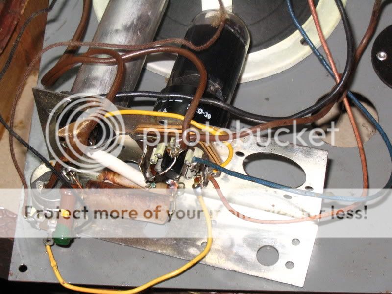
Further edit: The input coupling cap (which is all that's between you and the live supply) looks as though it's about to expire - note that nearly all the wax has melted off due to overheating, probably because of leakage
It's dangerous enough in its intended application, but there's much more chance of your coming into contact with potentially live connections if used as an instrument amp. You'd also run into severe hum problems if it's interfaced with other gear.
Crystal cartridges need a very high impedence to work into, so your lowish-impedence guitar pickup won't work well with this amp anyway.
Edit: The phono amp may possibly be run from an ancillary winding on the turntable motor, which is a bit safer, but you'd then have to fit a substitute transformer if you ditch the t/t.
Further edit: The input coupling cap (which is all that's between you and the live supply) looks as though it's about to expire - note that nearly all the wax has melted off due to overheating, probably because of leakage
The phono cartridge has 3 VOLTS of output, and the guitar has milliVolts - so you need more gain - typically two triode stages would be the minimum, though a single pentode might be enough.
But you MUST isolate this from the power line - the record player was safe enough (before the capacitors became leaky - believe me, they ARE). But as soon as you plug something else into it, you have a hazard - your next contact with a mike stand could be your last!
You CAN reuse the output transformer and speaker, using a power transformer or other isolation transformer, and it will be as safe as a modern amp.
Whodatpat,
Both dnsey and Tom Bavis are ABSOLUTELY CORRECT about the need for transformers in guitar service. Failure to heed the warning exposes the player to DEADLY danger.
Adding "iron" should be easy, once the motor and platter are removed.
As it turns out, Dame Fortune has smiled on you and turning that old thing into a guitar amp is quite feasible. 😉 The 'SJ7 based small signal circuitry in the Fender model 5C1, AKA "Champ", is more than capable of driving an O/P tube that mates with the O/P trafo that's present. That is just as well, since you will have reduce Fender's 250 KOhm plate load resistor value in order for proper function to occur, at the necessary lower B+ voltage.
Like the "Champ", your amp will use 2 signal tubes. They are a 12SJ7 and a 12L6. The 12L6 is close enough to the OEM tube's characteristics to mate well with the existing O/P "iron".
A "Rat Shack" Catalog # 273-1352 transformer will power the tube heaters. A Triad N68-X isolation trafo from Allied Electronics will power the B+ rail. Put a CL90 on the N68-X's primary side to tame the power on inrush. Bridge rectify the secondary of the N68-X with 4X UF4007 diodes. A LARGE 1st filter cap. is acceptable here. 160 V. at the 1st filter cap. is a very reasonable expectaction.
Guys,
FWIW, I did some digging and it is possible to have a tube rectified "spud" amp in these ancient record players.
Look up the 117L7/117M7, the 117N7, and the 117P7. The 3 types have a half wave rectifier and a beam power tetrode in a single envelope.
Bottom feeders rejoice! 😀
FWIW, I did some digging and it is possible to have a tube rectified "spud" amp in these ancient record players.
Look up the 117L7/117M7, the 117N7, and the 117P7. The 3 types have a half wave rectifier and a beam power tetrode in a single envelope.
Bottom feeders rejoice! 😀
Eli,
Dirt Cheap Champ is exactly what I am after.
I WILL NOT TRY THIS WITHOUT A POWER TRANSFORMER.
I can see where the OT and Speaker will go. What I dont understand is how to use the two transformers in place of the one on the power side.
Patrick
Dirt Cheap Champ is exactly what I am after.
I WILL NOT TRY THIS WITHOUT A POWER TRANSFORMER.
I can see where the OT and Speaker will go. What I dont understand is how to use the two transformers in place of the one on the power side.
Patrick
An externally hosted image should be here but it was not working when we last tested it.
Using a single transformer would be easier and perform better, but basically you would take two transformers size one large enough for the filaments and the plate current load reflected back to the 6.3V secondary of the second filament transformer which is connected as a step up..
So lets say you need 50mA at 300V and you have a 120V/6.3V transformer - this would be roughly equivalent to 15W, allowing for power factor in the rectifier circuit figure on 22W which conservatively can be handled by a 4.5 - 5A 6.3V filament transformer. Assume you need a further 2A for the filaments and this gives you roughly a 7A/6.3V filament transformer operating on the 120V mains, and a 5A 6.3V transformer configured as a step up. In practice you would probably just get two transformers with the higher rating.
This is only one way to skin the cat, take a look for small isolation 120V:120V transformers, even a smallish 25W or so version will work great here with a doubler. Find a small 2A or so 6.3V transformer for filaments.
If you want full wave tube rectification then you should get a conventional transformer with 5V rectifier filament winding, center tapped high voltage secondary (maybe 450 - 500Vct) and a 6.3V filament winding. Ones targeted to small fender se clones show up on eBay for short money all the time.
With a little scrounging you could actually build a very good clone of the fender champ for very little money - with virtually guaranteed results with a good output tranny and decent jensen reissue speaker or similar.
I can see where the OT and Speaker will go. What I dont understand is how to use the two transformers in place of the one on the power side.
Patrick,
You need to look at the schematic, as well as the pictorial. Please notice that the power trafo of the "Champ" has 3 windings: CT rectifier, 6.3 V. signal tube heater, and 5 V. rectifier filament. SS rectifying the B+ eliminates the need for the 5 V. winding. The R/S 273-1352 is a 12.6 VCT filament trafo that will energize the heaters of a 12SJ7 voltage gain block, and a 12L6 "final". The Triad N68-X has a simple, untapped, secondary. That's why a bridge rectifier is used. The primary sides of the 2 power trafos are connected in parallel to the AC mains. The N68-X is "universal" and has a pair of primaries. You wire the pair in parallel and connect 1 end to a CL90 inrush current limiter. The remaining ends of both the primary pair and the CL90 connect to the AC mains. The primary of the R/S filament trafo simply connects to the AC mains. The total cost for the 2 trafos given will be less than $25. I too am CHEAP. 😀
Let's look at the voltages around the 'SJ7 in the 5C1. The pictorial shows 130 V. on the plate and the other side of the 250 KOhm load resistor connected to 280 V. at g2 of the 6V6. So, 120 V. are dropped in 250 KOhms. Ohm's Law tells us the plate current must be 480 muA. Our B+ is "160" V. and it can't change. We have only 40 V. to drop in the load resistor. Ohm's Law says "83" KOhms is the correct load resistor value for our situation. 84.5 KOhms is the nearest available value that's not less than the computed value. To stay with that 1/3 factor, the 'SJ7 screen grid dropping resistor becomes 330 KOhms and the 50 nF. bypass cap. becomes 150 nF.
OK, the cabinet, masonite board, chassis bracket, speaker and O/P trafo are what's retained from the 1940s record player. All the rest gets discarded. That phenolic wafer Octal socket is pretty chintzy and should be replaced.
Before you toss anything, jot down the values of the parts around the tube. In particular, I need to know the values of the RC cathode bias network.
Are you still with me? 🙂
Eli Duttman said:
Are you still with me? 🙂
Nope, but I really want to be. For the most part i can follow the schematic and the layout picture is easy enough for, well me, to put together. But i have a hard time following the verbal descrription. I really want to do this project, but I also understand I really have a lot to learn along the way.
I will have a look at the tube in the current circuit and see what i can identify. (I'd be willing to mail the thing to you if it helps.)
Patrick
Eli Duttman said:
OK, the cabinet, masonite board, chassis bracket, speaker and O/P trafo are what's retained from the 1940s record player. All the rest gets discarded.
You'll want to know the impedance of that O/P trafo. It's eitehr 2K or 4K or 3K, and looking at the wiring of the tube socket, and looking at the RCA tube manual, I'd guess it's a 70L7. That tube specifies a 2K load. So the trafo would likely be 2K. If it's a 117L7 or 117P7, that would be 4K, or 117N7 wants 3K.
If it is a 70L7, that tube draws 150ma of heater current, and you could add other 150ma heater current tubes in series, like a 12AU6 or 12AX7 or 12AT7 or 12AU7 if you want more circuits for more gain and other guitar effects. Place the new tubes' heaters where the big white power resistor looks to be, from the 70L7 heater and ground.
As mentioned above, you MUST get and use an isolation transformer. Install it inside the cabinet so it never gets lost or separated from the amp.
You'll want to know the impedance of that O/P trafo. It's eitehr 2K or 4K or 3K, and looking at the wiring of the tube socket, and looking at the RCA tube manual, I'd guess it's a 70L7. That tube specifies a 2K load. So the trafo would likely be 2K. If it's a 117L7 or 117P7, that would be 4K, or 117N7 wants 3K.
WA2ISE, thanks for your comments.
I'm having Patrick switch to a 12L6GT, as the "final". Whatever that O/P trafo happens to be should be a reasonably good match for a 12L6.
The CT of the 12.6 V. filament trafo will be biased off of B+ at approx. 80 V. Doing that should provide some hum control.
Both power trafos will be mounted on the masonite board's underside. You are 100% correct about not forgetting them.
 is most definitely to be avoided.
- Status
- Not open for further replies.
- Home
- Amplifiers
- Tubes / Valves
- Duosonic 40's era record player