I am new to designing power supplies but I do believe that the are the most important part of an amplifier. I will mainly be working with tubes and for guitar applications so the power supplies are not that difficult. Under transformer properties it asks for rms voltage, is this the ct voltage like 700vdc for a 350-0-350? Every time input data I get a warning that says my piv is over 1500 for a 5u4gb. I guess I am hoping someone could just give me a run down on how to use the software. Also what looks like a bleed resistor in the circuit but they call it a load resistor. The info I am typing in is 750v for transformer to a 5u4gb full wave rectifer to a 22uf cap. I guess I am using the tool to try to see what b+ voltage I will expect from a specific transformer before I purchase the transformer. I am mainly looking at the 300 series from hammond 5u4gb rectified, and I want around 400 volts at the plate for a SE 6l6gc guitar amp build. Also I would like to add a choke after the reservoir cap before the plate of the 6l6gc so I know that it has to be able to handle the current but I can't figure out how to add a choke to the psu designer. I know if have the current draw for the amp I can use ohms law to determine voltage drop across the choke but it would be nice to use the psu designer.
Is the psu designer even worth using for my application?
Is the psu designer even worth using for my application?
Ok so I know I am a noob and did not take physics but their must be an equation to figure out the load in terms of resistance.
If you're doing a full wave rectifier, use the 350V figure. Make sure to include the right transformer resistance.
For the load, use Ohm's Law (R = V/I) to figure out the equivalent resistor.
For the load, use Ohm's Law (R = V/I) to figure out the equivalent resistor.
I guess my question is what voltage do I use (ac on secondary of ptf)? And the for the current part of the equation do I use the total consumption of the B+ ?
Yes, you must use a load resistor equivalent to the total B+ consumption. To find out the correct power transformer secondary AC voltage needed to get a specific rectified DC (B+) voltage under load you must try many runs (trial and error process) with different transformer voltages because PSUDII can't work backwards and give you the transformer AC voltage needed for a specific filtered DC target.
Another important point with PSUDII when you simulate a circuit using tube rectifiers is to cross the SOFT START in the option menu, otherwise you may get repeated excessive peak current warnings during the switch-on transient. (It is allways recommended to allow warnings in PSUDII) This feature is to simulate the slow warm-up of tube rectifiers.
Another important point with PSUDII when you simulate a circuit using tube rectifiers is to cross the SOFT START in the option menu, otherwise you may get repeated excessive peak current warnings during the switch-on transient. (It is allways recommended to allow warnings in PSUDII) This feature is to simulate the slow warm-up of tube rectifiers.
Last edited:
Make sure your voltage is set to 120V. My version defaults at 230V for the primary.
Also, you really need to know how much current your stages are drawing to model correctly.
Also, you really need to know how much current your stages are drawing to model correctly.
Famous: You can change the load from resistive to constant current by right clicking on the load section (not just the load R) and change the load to constant current. Then input your estimated current draw. If you want to get fancy, you can simulate each stage's current draw with multiple current taps. Constant current load is more intuitive at least for me.....
For FWCT rectification, the PIV is 2 X (sqrt 2) X transformer secondary voltage, so for a 350-0-350 transformer it's around 1000V or so. If you were using 750V as your transformer voltage, you would exceed the 1500V 5U4 rating, but that implies a transformer rating of 750-0-750, which isn't what you want.
For a CLC topology, right click and add an LC section after the first cap. Can you post your circuit schemo and the PSUD schemo?
Thanks all for the help, I was not right clicking on anything and I was missing a whole lot of options. And for the 350-0-350 transformer I was typing in 750 for T1 thats how I was getting piv warnings, after changing to 350 the model looks a lot better. I know my current draw for both sections (their will be one ecc83 for the preamp and one 6l6gc for the power tube) I just needed to change to constant current load.
Thanks again, I will post some schemo's when done
Thanks again, I will post some schemo's when done
You must be very careful when using constant current loads in your simulation. I noticed with PSUDII that CCL's sometimes can play havoc with the program and generates false,strange or impossible results. Better to use a resistive load corresponding to the current drawn by your circuit at the nominal working voltage. Results will be more consistent and in accordance with real life working of your circuit.
Before using any circuit simulation software you must be aware of all his limitations and fully understand the meaning of all the parameters involved.
Before using any circuit simulation software you must be aware of all his limitations and fully understand the meaning of all the parameters involved.
Does anybody know a way to share my PSU II design on this forum?
Assuming windows, Control V, Control P (cut and paste into paint).....
Then crop, resize to less than 200Kb, and save as a JPEG, BMP, etc.
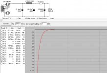
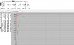
I will just write the info and if someone wants to plug it in on their PSU II designer that would be cool. So T1 is 350v (33ohms) going into a 5U4GB full wave rectifier. Then:
C filter- C1 40uf (2ohm)
LC filter- L1 is 5H (105ohm) C2 is 40uf (2ohm)
RC filter-R1 is 4.7k C3 is 22uf (2ohm)
I used 8k as a resistive load
The choke I want to use is hammond 159Q rated for 150ma and 500v. I want to feed the Plate of the 6l6GC after the choke and feed the 12AX7 after the 4.7k resistor. Does this look right or am I way off? The simulator readings for mean voltages are:
C1-434v
C2-428v
C3-250v
I don't know how to choose the resistive load but I got 8k from dividing 450 (estimated B+) by .055 (6l6 and 12ax7 current draw).
The program does nothing when I hit control V or Control P, maybe because I am using windows 7? Also when I save a design I can't open it up after because my computer "can't find" the program that created it.
Sorry, try ALT-PRINTSCREEN in PSUD, then CONTROL-V in paint.
Then resize to less than 200K, then save as JPEG.
Then resize to less than 200K, then save as JPEG.
Attachments
Last edited:
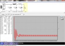
What's the proposed current draw for the 12AX7 and the 6L6GC? (each separately)
Assuming 6L6GC is 50ma and 12AX7 is 5ma.........use current taps in PSUD
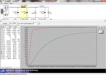
The ringing indicates a flappy supply, not good for hifi but may be what you want for guitar.......increasing the value of C2 will stiffen up the supply and reduce ringing.
Assuming 6L6GC is 50ma and 12AX7 is 5ma.........use current taps in PSUD
The ringing indicates a flappy supply, not good for hifi but may be what you want for guitar.......increasing the value of C2 will stiffen up the supply and reduce ringing.
Attachments
Last edited:
Well if the plate voltage is at 428v The 6l6gc should be around 50ma for 20w. As far as the 12ax7 I don't think it will draw more than a few milliamps.
Well if the plate voltage is at 428v The 6l6gc should be around 50ma for 20w. As far as the 12ax7 I don't think it will draw more than a few milliamps.
That was my guess....see post 15 above, I just edited the PSUD model.
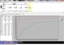
A 100uf at C2 does look better. Thanks for your help Boywonder, you saved me hours of pulling my hair out.
Jason
Jason
Attachments
Last edited:
- Status
- Not open for further replies.
- Home
- Amplifiers
- Power Supplies
- Duncan amps PSU designer II help