Hi donpetru,
Power amplifiers are classified by the position of the operating point on the transfer characteristic of the output device.
Class C below cut-off
Class B at cut-off
Class AB above cut-off
In class B the device conducts 50% of the cycle, commonly a pair in push-pull arrangement, both shut off when no signal is present, giving low power consumption, high efficiency and high maximum current drive capability. This operating mode introduces significant time errors and distortion to the signal as it moves through the zero crossover point. Switching distortion is created by completely turned off and turned on devices, depending on several variables, that is output topology, device speed, current, temperature and the driver`s ability to provide controlling charge. The switching speed is determined by the time required for the charge carriers to travel across the semiconductor region. The rapid change of control voltage triggers high slew rates and peak currents. The so-called "non-switching" amplifiers maintaining a small quiescent current are considered class B. An absence of switching distortion does not mean an absence of crossover distortion.
In class AB the device conducts less than 100% but more than 50% of the cycle. A less than 100% conduction of the cycle means various additional nonlinearities, giving a distinctive difference in distortion pattern. Crossover distortion is caused by nonlinear transfer and switching effects and a nonsmooth transition between devices. Class AB is an over-biased class B, giving class A operation up to a certain power level, over that, the device begins to cut off and distortion rises. Crossover distortion implies most disagreeable odd high order harmonics, increasing with falling signal amplitude, followed by much higher level of intermodulation products, increasing with signal complexity. Cross-conduction (simultaneous conduction) allows brief transient currents to flow. An excessive amount of negative feedback is needed to reduce crossover distortion because of the poor loop gain in the area. Numerous attempts have been made to alleviate crossover distortion by other correction techniques, like error feedforward and active error feedback.
In class A, the devices operate in their linear region, having output current flow for the whole cycle of the input signal, therefore one device is adequate, like in the single-ended unbalanced circuit, where the signal is referred to ground and is asymmetric with reference to ground, or in a balanced circuit, two devices operating in phase opposition, where the signal is balanced to ground and is symmetric with reference to ground. The device current varies between twice the quiescent current and zero.
Only class A and class AB provide a satisfactorily faithful reproduction of the input signal.
Load impedance, emitter resistance, DC current transfer ratio are not determining factors for operating class.
Sorry for the impolite remark.
I believe you are referring to Bipolar output stages.
Even then, it is a matter of opinion as to what constitutes
best. That approach is good if you are looking for the
lowest harmonic distortion measurement at the transition
point, but there are those who argue that a higher bias
point sounds better.
😎
Yes you're right, I was addressing bipolar stages, for smoothest take-over as measured or seen on a scope. Of course there is always the x-factor that makes you prefer the sound of another (higher) bias point, which may be different for different people. The final arbiter is the sound you prefer, I fully agree Nelson.
jd
Hi donpetru,
Power amplifiers are classified by the position of the operating point on the transfer characteristic of the output device.
Class C below cut-off
Class B at cut-off
Class AB above cut-off
In class B the device conducts 50% of the cycle, commonly a pair in push-pull arrangement, both shut off when no signal is present, giving low power consumption, high efficiency and high maximum current drive capability. This operating mode introduces significant time errors and distortion to the signal as it moves through the zero crossover point. Switching distortion is created by completely turned off and turned on devices, depending on several variables, that is output topology, device speed, current, temperature and the driver`s ability to provide controlling charge. The switching speed is determined by the time required for the charge carriers to travel across the semiconductor region. The rapid change of control voltage triggers high slew rates and peak currents. The so-called "non-switching" amplifiers maintaining a small quiescent current are considered class B. An absence of switching distortion does not mean an absence of crossover distortion.
In class AB the device conducts less than 100% but more than 50% of the cycle. A less than 100% conduction of the cycle means various additional nonlinearities, giving a distinctive difference in distortion pattern. Crossover distortion is caused by nonlinear transfer and switching effects and a nonsmooth transition between devices. Class AB is an over-biased class B, giving class A operation up to a certain power level, over that, the device begins to cut off and distortion rises. Crossover distortion implies most disagreeable odd high order harmonics, increasing with falling signal amplitude, followed by much higher level of intermodulation products, increasing with signal complexity. Cross-conduction (simultaneous conduction) allows brief transient currents to flow. An excessive amount of negative feedback is needed to reduce crossover distortion because of the poor loop gain in the area. Numerous attempts have been made to alleviate crossover distortion by other correction techniques, like error feedforward and active error feedback.
In class A, the devices operate in their linear region, having output current flow for the whole cycle of the input signal, therefore one device is adequate, like in the single-ended unbalanced circuit, where the signal is referred to ground and is asymmetric with reference to ground, or in a balanced circuit, two devices operating in phase opposition, where the signal is balanced to ground and is symmetric with reference to ground. The device current varies between twice the quiescent current and zero.
Only class A and class AB provide a satisfactorily faithful reproduction of the input signal.
Load impedance, emitter resistance, DC current transfer ratio are not determining factors for operating class.
Sorry for the impolite remark.
Hi Lumba,
Good overview. I only want to comment on your last sentence. Load impedance is a factor in the class of operation. If you give me a class A amp, I make it into a class AB amp by just changing the load impedance. Similarly, give me a class AB amp and I make it into a class A amp by changing the load impedance.
Take a 10W class AB amp for an 8 ohm speaker, load it with a 100 ohms headphone instead of a speaker and presto! a class A headphone amp !😀
I know that this is not normally the way it is done, but I thought it would help to understand the differences.
jd
yes, the ClassA rating is purely a current output consideration.
This depends very much on load.
This depends very much on load.
Hi Lumba Ogir,
I knew what you say in post no.41 (on the class A, B and AB).
In addition, I think you not completely understood when I referred to the amplifier load, hfe and I_bias. In class A, power losses are high and creating audio amplifier class A is justified only for low power amplifier. Efficiency class A amplifier is approximately 25%, class AB 50% and class B 75% (theoretical).
Hi Janneman,
Referable to your words in post No. 29
Any audio amplifier has two operating modes:
a) unloaded running (or idle);
b) loaded running.
In other words, we have a stationary operation mode and transient operation mode. You mean we can make an amplifier in class B in a stationary operation mode (unloaded running) and it will function in class A in transient operation mode. It's very accurate, so it can happen. But always operating mode for an audio amplifier is established in stationary operation mode (unloaded running). In this stationary operation mode is very important to establish a class amplifier with the V_bias value.
And yes, in diagram class A posted by me (somewhere on page 2 of this topic), if you change load transistor (in the emitter or collector), you can change the class of amplifier operation. In fact, this relates to the user janneman, in his last post above.
Regards
Hi Lumba Ogir,
I knew what you say in post no.41 (on the class A, B and AB).
In addition, I think you not completely understood when I referred to the amplifier load, hfe and I_bias. In class A, power losses are high and creating audio amplifier class A is justified only for low power amplifier. Efficiency class A amplifier is approximately 25%, class AB 50% and class B 75% (theoretical).
Hi Janneman,
Referable to your words in post No. 29
Any audio amplifier has two operating modes:
a) unloaded running (or idle);
b) loaded running.
In other words, we have a stationary operation mode and transient operation mode. You mean we can make an amplifier in class B in a stationary operation mode (unloaded running) and it will function in class A in transient operation mode. It's very accurate, so it can happen. But always operating mode for an audio amplifier is established in stationary operation mode (unloaded running). In this stationary operation mode is very important to establish a class amplifier with the V_bias value.
And yes, in diagram class A posted by me (somewhere on page 2 of this topic), if you change load transistor (in the emitter or collector), you can change the class of amplifier operation. In fact, this relates to the user janneman, in his last post above.
Regards
Hi donpetru,
I was not talking about any load resistor in a transistor collector or emitter. I was talking about the load resistance or impedance formed by the speaker.
Let us say the amplifier has a certain Ibias, let us say 1A. That means that the amplifer can deliver max pos Iout of 2A before the 'P' transistor is cut off. Also, it can deliver -2A before the 'N' transistor is cut off. Therefore, the amplifier can deliver +/- 2A peak = 1.4A RMS to the load in class A.
Now if I have a 4 ohm speaker, and I want to drive the speaker with an output signal of 12V RMS, that speaker needs 12/4=3A RMS. That means that the amplifier has to deliver current above the class A region, so when the Iout goes above 1.4A the amplifier goes into class AB. If the speaker is 8 ohms, it can drive the speaker till 11.2V RMS in class A, so for 12V RMS it just gets into AB. So you see that for a given amplifier the class depends also on the load.
If the amplifier has an Ibias of 2.5A, the Iout in class A, RMS, is 2.5*2/sqrt2=3.5A rms so this amplifier can drive a 4 ohm speaker to 12V RMS in class A with some reserve.
Does that make sense?
jd
Just a short input on this: Class A is almost always best, but not really necessary, because most people do not drive their amplifiers into clipping. What good is it to have an amp that is class A, 1 dB or so below voltage clipping and then clip it on the next note?
However, most here do not realize that Class AB is really class B, once you go beyond the class A bias. Then, the even harmonics that were so neatly cancelled out by class A operation, become instead, higher order odd harmonics that add to the existing higher order harmonics.
My test, and I have a switch on the JC-1 power amp to prove it, is the change in higher order 7th harmonic, between the Class AB1(25W Class A) and the Class Ab2 setting (maybe 1/10W Class A), at let's say 10W into 8 ohms.
Flip the switch, and there is MORE 7th harmonic in the Class AB2 position. Not much more, but it is distinctly measurable.
Only class A and class AB provide a satisfactorily faithful reproduction of the input signal.
According to my own experience, class A+C is much better approach than class AB.
Just a short input on this: Class A is almost always best, but not really necessary, because most people do not drive their amplifiers into clipping. What good is it to have an amp that is class A, 1 dB or so below voltage clipping and then clip it on the next note?
However, most here do not realize that Class AB is really class B, once you go beyond the class A bias. Then, the even harmonics that were so neatly cancelled out by class A operation, become instead, higher order odd harmonics that add to the existing higher order harmonics.
My test, and I have a switch on the JC-1 power amp to prove it, is the change in higher order 7th harmonic, between the Class AB1(25W Class A) and the Class Ab2 setting (maybe 1/10W Class A), at let's say 10W into 8 ohms.
Flip the switch, and there is MORE 7th harmonic in the Class AB2 position. Not much more, but it is distinctly measurable.
Fully agree to that John. It is difficult to reason where the take-over from A to AB should be, because you can't really map the changes in harmonic structures, that change during the traject from A to B, into a sound. There is also a disctinct change in open loop gain at the transition point of A to B itself, because you go from both active devices contributing to only one (the N or the P) so around that point you have a change in harmonic structure as well. It also depends on your listening habit, type of music, level etc. In the end it may boil down to just listening and decide based on that.
jd
Allrighty then: I try to draw the drawings, but I can see it hasn't yet sunk in...
And still we dance in circles without addressing the proper meat of this issue.
An ideally linear (or at the very least, even order cancelling) class A amplifier, can
rarely become an ideally non-linear (smooth crossing) Class AB amplifier merely by
dialing down the quiescent current alone. The curves required are quite different
in shape. Class A best not be curved at all... Class AB possibly square law is best?
Class A that suddenly cuts in and out of B at some level is utterly useless. I don't
see how that would ever qualify as worthwhile AB? Thats just a clipping of another
sort... You can't get to a proper AB crossing from pure A merely by dialing down a
quiescent. It takes a specific non-linearity that wouldn't be optimum for class A.
Error corrected crossing technique like Hawksford the only exception that comes
quickly to mind... Might adapt within reason to either situation.
Allrighty then: I try to draw the drawings, but I can see it hasn't yet sunk in...
And still we dance in circles without addressing the proper meat of this issue.
An ideally linear (or at the very least, even order cancelling) class A amplifier, can
rarely become an ideally non-linear (smooth crossing) Class AB amplifier merely by
dialing down the quiescent current alone. The curves required are quite different
in shape. Class A best not be curved at all... Class AB possibly square law is best?
Class A that suddenly cuts in and out of B at some level is utterly useless. I don't
see how that would ever qualify as worthwhile AB? Thats just a clipping of another
sort... You can't get to a proper AB crossing from pure A merely by dialing down a
quiescent. It takes a specific non-linearity that wouldn't be optimum for class A.
Error corrected crossing technique like Hawksford the only exception that comes
quickly to mind... Might adapt within reason to either situation.
Well, class A doesn't 'suddenly cut in or out of B', it isn't as bad as that sounds, it is gradually.
My experience with my Hawksford error correction amp (see AX issues Aug and Sept 2009) is that people do think it sounds like a class A amp, based on some informal demo's for non-technical but experienced listener people (they had no idea what ec actually is).
When you measure that amp, the cross-over distortion is not extremely low and looks like a lot of other good amps. I'm still not sure what the effect of the ec is exactly but it may have something to do with the smoother transfer of A to B.
jd
because you go from both active devices contributing to only one (the N or the P) so around that point you have a change in harmonic structure as well.
Exactly why I suggest AB's use two error corecting followers with fixed
voltage offset. And correction determined by comparator devices not
under stress, nor thermal tracked to the output transistor in any way...
Allison, Hawksford, and/or Emitter coupled Alephs are all quite suitable.
I can abuse discrete diodes, rather than emitters to smooth crossing.
The push and pull diode can be of exactly the same type... And they
present curves freed of thermal errors that surely exist in the actual
power devices, if left to do thier own non-linear things uncorrected.
There need not be any apparent difference in N or P behavior around
the crossing point when so designed... True compliment is engineered,
rather than left to chance matching of hot active components.
Error corrected crossing technique like Hawksford the only exception that comes
quickly to mind... Might adapt within reason to either situation.
You may very well be on to something here......despite the extra complexity.😉
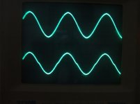
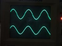
For example... These waveforms are from an EC hexfet follower stage I've been playing with, here bias is class B, with the signal peak at ~2.5A, 5KHz. Of the two waveforms in each photo, the gate drive is the top waveform and the output is the bottom. The first photo is with the error correction disabled. The crossover dead time is clearly visible. The second photo is with the EC enabled and you can see how steep the slope of the gate drive signal becomes at crossover in order to 'cancel' all the crossover distortion. Not technically cancel all of it but the crossover is hardly visible in the output even with class B bias. As frequency increases, the EC has to work harder (faster), but with it you can make the crossover of a proper bias class AB seemingly flawless.
Attachments
Last edited:
Exactly why I suggest AB's use two error corecting followers with fixed
voltage offset. And correction determined by comparator devices not
under stress, nor thermal tracked to the output transistor in any way...
Allison, Hawksford, and/or Emitter coupled Alephs are all quite suitable.
I can abuse discrete diodes, rather than emitters to smooth crossing.
The push and pull diode can be of exactly the same type... And they
present curves freed of thermal errors that surely exist in the actual
power devices, if left to do thier own non-linear things uncorrected.
There need not be any apparent difference in N or P behavior around
the crossing point when so designed... True compliment is engineered,
rather than left to chance matching of hot active components.
Sounds good in principle, but I would be surprised if it would work well. In practise, it is extremely difficult to change or add some devices at a specific point of the waveform. It is almost impossible to avoid some discontinuity or spike. But, no guts, no glory 😉
jd
This drawing is rather oversimplified, but effective as an example...
Apologies to Nelson for abusing his Alephs in such a crude manner.
Got two nodes that rigidly follow one emitter above and below the input.
Because the quiescent set networks contain only resistors, there is no
thermal runaway issues, but also there is no possibility for smooth AB.
It simply doesn't have the required non-linearity for such a crossing...
Sloped resistively for A, it suffers AB worst because it is way TOO linear.
But add an MBR745 Schottky in series with each of R3 & R4, and tweak
each resistance value to around .12ohms. You now get the same curves
I posted a page or two ago. Smoothest crossing one could ever hope.
Its riding the curve of quasicomplimentary diodes does the AB magic...
------------------------------------------------
Now, you can get the same magic with power transistor emitters, or
MOSFETs with square law, or whatever... But try to match P and N!
Not merely matching in full class A, but also in near cutoff, and at
every temperature. I say power device non-linearity can't be relied
upon to get this right... Nor just turning down the quiescent on any
old A...
Attachments
Last edited:
all ClassAB amplifiers do this and many do it very successfully..........Class A that suddenly cuts in and out of B at some level is utterly useless. I don't
see how that would ever qualify as worthwhile AB?
If the amplifier is biased to optimal Vre to attenuate the crossover distortion then the results can be superb.
This change from A to B applies whether the optimal bias current is 20mA or 200mA or 1500mA. Each ClassAB amplifier design should be set up such that Vre <=26mVre (note this must include the internal R of the transistor and the effect of Rb and any source impedance feeding the output stage, not just the external Re value).
Some misinterpretation between classes comes from the fact that the class distinction reports to single devices first. In a push-pull, classification applies to the bias of each branch only, which most often is the same for both, but not necessariyl. At least, an example of a push-pull exists where branches are not similarly biased : one in class A, the other in class C :
http://www.angelfire.com/ab3/mjramp/pagefour.html
Lumba Ogir,
---In class B the device conducts 50% of the cycle---
This is almost impossible to achieve because there is no abrupt switching, even with bipolars, which would allow it
(the closest approach to it is the Blomley amp, I think).
So the definition for a class B push-pull amp has to rely to a chosen threshold of conduction for each branch. It is conveniently to choose it where the crossover distorsion is minimised. More bias qualifies the class AB where visible traces of the doubling transconductance effect start to be seen.
JAN
---My experience with my Hawksford error correction amp (see AX issues Aug and Sept 2009) is that people do think it sounds like a class A amp, based on some informal demo's for non-technical but experienced listener people (they had no idea what ec actually is).
When you measure that amp, the cross-over distortion is not extremely low and looks like a lot of other good amps.---
Probably, the remaining distorsion is a bit similar to the one in the Quad Current Dumping amps : some traces of switching. However I should think that the purpose of EC is to remove the greatest part of distorsion due to non-linear variations of the output stage gm.
JAN
---My experience with my Hawksford error correction amp (see AX issues Aug and Sept 2009) is that people do think it sounds like a class A amp, based on some informal demo's for non-technical but experienced listener people (they had no idea what ec actually is).
When you measure that amp, the cross-over distortion is not extremely low and looks like a lot of other good amps.---
Probably, the remaining distorsion is a bit similar to the one in the Quad Current Dumping amps : some traces of switching. However I should think that the purpose of EC is to remove the greatest part of distorsion due to non-linear variations of the output stage gm.
Possibly. There is also a separate ec loop for the input- and Vas stage.
Then again, it may also be my smart grounding scheme 😀
jd
- Status
- Not open for further replies.
- Home
- Amplifiers
- Solid State
- dumb question about class AB