Here's a dumb idea that I threw together in Eagle, a low power UcD implementation.
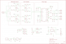
Left to right:
- Differential receiver stage. Copied from my Boominator amp design, blocks ground loop noise and provides simple 1st order highpass/lowpass filtering.
- Differential-feedback UcD comparator stage using TLV5602D.
- TI TAS5103 digital-input, BTL-output power stage.
Power supply is 12V-20V range, single ended.
A supervisor/reset IC in the lower right handles on/off switching as well as amplifier fault protection. LED1 is lit if the amplifier's running, and blinks off in fault conditions.
NXP's UcD patent license requires you to use 'enabling' NXP components in your design - provided the 2N7002 FET that controls the LED is sourced from them (I can't find any other parts on the card that can come from NXP) I hope we're OK 😉
No idea if this will work. The design assumes that positive PWM_A into the TAS causes OUTA to switch to PVCC, I'll probably have to make some kind of configurable strapping for the feedback - or hopefully instead someone's got a TAS5103 evaluation kit and a 'scope and can measure the behavior 🙂 And who knows, the TAS might overcurrent trip off before it gets a chance to start oscillating...
Thoughts/comments?
Attachments
Member
Joined 2009
Paid Member
Wow, that's a pretty serious design. Multilayer PCB, CPLD following the comparator, DC detection using optocouplers...
I'll give it a thorough read when I've got more time, might be some ideas I can rob from it.
I'll give it a thorough read when I've got more time, might be some ideas I can rob from it.
- Status
- Not open for further replies.