Hi,
Some time ago I got interested in building a Gilmore headphone amp [1]. I'd like to power it from using a SuperRegulator. As I understand it, this amp requires well matched positive and negative supply voltages. Mr. Gilmore's powersupply uses an inverting power opamp to achieve this. All the SuperRegulator designs that I have seen only provide a single voltage, so getting a good match between the positive and negative side would require quite some resistor matching and tuning. Then one can only hope the whole thing doesn't drift too much due to temperature change and such.
I thought I'd slap together a positve and negative SuperReg, but replace the voltage reference with an opamp inverting the positive voltage reference. The advantage would be that no resistor tuning is required. Also, any drifts in the reference will be copied to both rails. It still requires resistor matching, but 0.1% resistors in the critical places should do.
What drawbacks are there to this approach? Is it worth persuing?
Thanks,
Alfred
[1] http://headwize2.powerpill.org/projects/showproj.php?file=gilmore3_prj.htm
Attachments
"What drawbacks are there to this approach? Is it worth persuing?"
Fears about the necessity the supply voltages being matched and tracking each other unfounded. The tracking on the current sources is much more important than the supply voltages. If one wants to do something to improve this supply I would put my efforts into bypassing the adjustment terminals for the regulators and filtering the reference noise with the right value caps.
Starting with a 48 V supply is unnecessary and will destroy the regulators if the input to ADJ becomes greater than 30 something volts (check data sheets for exact numbers). Worrying about drifts and matching of a few millivolts is a waste of time. A decent op amp cost as much as or more than another voltage reference like the LM329. I can't see any advantage to it other than the fact that perhaps he didn't think of how to get of a negative voltage from a REF 02 series voltage reference. Most people use shunt references like the LM329 which make it a no brainer for a negative reference.
Claims of open loop distortion products less than 80 dB and line rejection of 120 dB are kind of unlikely. The voltage changes of this amount on the output of the regulator from noise on the input of the regulator would be well below the noise floor and difficult to verify. I believe the Jung type regulator would be a real improvement over this supply. The positive supply tracking the negative extremely closely is a non-issue. Even the supply shown in the article could be greatly improved with a few capacitors and resistor.🙄
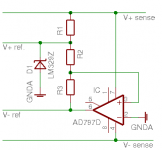
I'm not planning to upgrade the regulator proposed by Mr. Gilmore - I don't even want to use it. I want to replace it with a Jung type reg.If one wants to do something to improve this supply I would put my efforts into bypassing the adjustment terminals for the regulators and filtering the reference noise with the right value caps.
Drifts, okay, 10ppm/K is not enough to make me worry. Matching, however, is. In the LM329 datasheet, it says Vz is between 6.6 and 7.25V, 6.9V typically. Worst case scenario for a +-14V supply would be 1.32V difference. That's 4.7%. This, to me, seems like a lot.Worrying about drifts and matching of a few millivolts is a waste of time.
Of course, in the Jung circuit, it could be solved by tuning the voltage dividing resistor pairs. Resistors are cheap, so buying a metric boatload is not a problem. Solving Vout = Vref * (1+r1/r2) and (r1*r2)/(r1+r2) = 500 for r1 and r2 gives r1 = 500 Vout/Vref and r2 = 500 Vout/(Vout-Vref). Aiming for Vout = 14V and Vref between 6.6 and 7.25V gives 965.5 < r1 < 1060.6 and 945.9 < r2 < 1037.0 Ohm, which is still quite a range. Maybe a ~950 Ohm resistor plus a precision trimmer?
since you are quite serious about this........
"Of course, in the Jung circuit, it could be solved by tuning the voltage dividing resistor pairs."
I think if you buy a batch of LM329s you will find less than a couple of tenths of volts between devices. If really want to trim the supplies that close, put a much larger resistor than the value between the reference and it's filter cap, across the filter cap to ground to form a voltage divider for the small difference in reference voltages.
 WHAT EVER YOU DO, MAKE ABSOLUTELY SURE THAT YOU THERMALLY COUPLE THE LM329S (SELECTED FOR CLOSELY MATCHED TEMPCO) TOGETHER IN THE FIINAL CIRCUIT. MEASURE THE FILTER CAPS LEAKAGE CURRENTS TO MAKE SURE THEY ARE EQUAL. I WOULD LET THE CAPS SIT AT THE VOLTAGE THEY ARE TO BE USED AT FOR AT LEAST A WEEK AT MAYBE 35 TO 50 DEGREES CENTIGRADE BEFORE EVEN BEGINING TO MATCH THE LEAKAGE CURRENT. BE VERY CAREFUL TO USE RESISTORS WITH A TEMPERATURE COEFFICIENT NO MORE THAN 25 PPM/C, ACTUALLY 10 PPM/C WOULD BE PREFERABLE.
http://www.eeel.nist.gov/
"Of course, in the Jung circuit, it could be solved by tuning the voltage dividing resistor pairs."
I think if you buy a batch of LM329s you will find less than a couple of tenths of volts between devices. If really want to trim the supplies that close, put a much larger resistor than the value between the reference and it's filter cap, across the filter cap to ground to form a voltage divider for the small difference in reference voltages.
WHAT EVER YOU DO, MAKE ABSOLUTELY SURE THAT YOU THERMALLY COUPLE THE LM329S (SELECTED FOR CLOSELY MATCHED TEMPCO) TOGETHER IN THE FIINAL CIRCUIT. MEASURE THE FILTER CAPS LEAKAGE CURRENTS TO MAKE SURE THEY ARE EQUAL. I WOULD LET THE CAPS SIT AT THE VOLTAGE THEY ARE TO BE USED AT FOR AT LEAST A WEEK AT MAYBE 35 TO 50 DEGREES CENTIGRADE BEFORE EVEN BEGINING TO MATCH THE LEAKAGE CURRENT. BE VERY CAREFUL TO USE RESISTORS WITH A TEMPERATURE COEFFICIENT NO MORE THAN 25 PPM/C, ACTUALLY 10 PPM/C WOULD BE PREFERABLE. http://www.eeel.nist.gov/
I wasn't so serious.........
RE:since you are quite serious about this........
Everything in caps after the exclamation icon was satire.........Sorry.
RE:since you are quite serious about this........
Everything in caps after the exclamation icon was satire.........Sorry.
Re: I wasn't so serious.........
I'm admittedly new to electric engineering, but I do have a solid physics background. I'm capable of logic thought. I do appreciate your (serious) comments.
That being over with: your suggestion of a resistor across the reference's filter cap would allow me to tune a reference voltage down. It's a nice solution, but not very flexible.
I'm putting a small trimmer pot with the wiper on signal ground between the two resistors to the inverting inputs of my two opamps (R9 in the ALW schematic). That way I can adjust the gnd to be exactly in between the two rails. The drawback is that I no longer have a real star ground.
Alfred - wonders if he's actually listening to what Fred is saying
Really?Everything in caps after the exclamation icon was satire.........Sorry.
I'm admittedly new to electric engineering, but I do have a solid physics background. I'm capable of logic thought. I do appreciate your (serious) comments.
That being over with: your suggestion of a resistor across the reference's filter cap would allow me to tune a reference voltage down. It's a nice solution, but not very flexible.
I'm putting a small trimmer pot with the wiper on signal ground between the two resistors to the inverting inputs of my two opamps (R9 in the ALW schematic). That way I can adjust the gnd to be exactly in between the two rails. The drawback is that I no longer have a real star ground.
Alfred - wonders if he's actually listening to what Fred is saying
I was wondering about this PSU / amp combo....
Hi Hegestratos,
I was wondering if anyone had used ALW's super reg with the KG class A amp....
Please keep me / us posted as to how you get on, and good luck with the build.
Best Regards
Sheriff
Hi Hegestratos,
I was wondering if anyone had used ALW's super reg with the KG class A amp....
Please keep me / us posted as to how you get on, and good luck with the build.
Best Regards
Sheriff
Re: I wasn't so serious.........


Fred, it's rather pointless if the reciever doesn't understand or probably not understandFred Dieckmann said:Everything in caps after the exclamation icon was satire.........Sorry.
hegestratos, I think the Gilmore amp can do very well with two ordinary Jung Regulators. I see no need for tracking voltages.
You may also use LM431 with a little bit more precision. 431 has more noise but I'll doubt that this is a big problem.
Maybe you should join the ALW group order?
http://www.diyaudio.com/wiki/index.php?page=ALW+regulator+pcb+group+buy
You may also use LM431 with a little bit more precision. 431 has more noise but I'll doubt that this is a big problem.
Maybe you should join the ALW group order?
http://www.diyaudio.com/wiki/index.php?page=ALW+regulator+pcb+group+buy
alw group buy finish date
Hi P-A,
I thought that the finish date for the group buy was the 21st of March.
I would have been up for 4 x pos, and 4 x neg.
Sheriff
Hi P-A,
I thought that the finish date for the group buy was the 21st of March.
I would have been up for 4 x pos, and 4 x neg.
Sheriff
We may have missed the boat
Hi P-A,
According to Mark Stone its the 21st...
http://www.diyaudio.com/forums/showthread.php?s=&threadid=28137&perpage=15&pagenumber=8
Sheriff
Hi P-A,
According to Mark Stone its the 21st...
http://www.diyaudio.com/forums/showthread.php?s=&threadid=28137&perpage=15&pagenumber=8
Sheriff
Hi folks.
I'm not buying the ALW boards, though I thought about it. Main reason: I want it to be mine. All mine. Queue evil laughter and loud doh. This way, I can put it on a eurocard too. I'm now waiting for the last components to arrive. Hopefully they'll be in this week. Then it's time for some alchemy with PCBs. I've got a design for the regulator and amp ready to go. I'll post pictures and such when I'm done.
Maybe I was a bit over-enthusiastic. It's basically my second electronics project, after a dead-simple bench powersupply. Here's hoping it'll all work.
Cheers, Alfred
We are rooting for you...
Hi Alfred,
Well i for one am rooting for you....
Cant wait to see how it works out.....
Keep us up to date
Cheers
Sheriff
Hi Alfred,
Well i for one am rooting for you....
Cant wait to see how it works out.....
Keep us up to date
Cheers
Sheriff
Re: We may have missed the boat

Sorry, I was mixing it up with my own regulator group buy.Sheriff said:Hi P-A,
According to Mark Stone its the 21st...
http://www.diyaudio.com/forums/showthread.php?s=&threadid=28137&perpage=15&pagenumber=8
People who live in glass houses
"Fred, it's rather pointless if the reciever doesn't understand "
Oh, I don't know..................... there are many of your post where I thought you must be kidding. My satire is not that subtle. It is pretty obvious to most people when I am kidding. Mark Twain said that there
is no satire so broad that somebody won't take it for absolute fact. Maybe you are one of those people.
You surely can't pretend to be innocent of ever having a little fun along these lines. You had to be kidding about putting down a $50 deposit to build a beta version of your power supply.......... right?

Why can't I register for your forum? I have tried twice. Does one have to be invited to join the forum? Even just to read it and not post?
http://instantboard.com/users/peran...&start=0&sid=dd1744c9f47b69b8805b4420964a0927
"Fred, it's rather pointless if the reciever doesn't understand "
Oh, I don't know..................... there are many of your post where I thought you must be kidding. My satire is not that subtle. It is pretty obvious to most people when I am kidding. Mark Twain said that there
is no satire so broad that somebody won't take it for absolute fact. Maybe you are one of those people.
You surely can't pretend to be innocent of ever having a little fun along these lines. You had to be kidding about putting down a $50 deposit to build a beta version of your power supply.......... right?
Why can't I register for your forum? I have tried twice. Does one have to be invited to join the forum? Even just to read it and not post?
http://instantboard.com/users/peran...&start=0&sid=dd1744c9f47b69b8805b4420964a0927
Re: We are rooting for you...
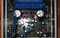
It worked! Amazing. I was thrilled. Then, I accidentally short-circuited the positive side for a very short period of time. After some measuring, I concluded the AD825 had blown up. Today, I got the replacement, and it's working again! It gives a stable plus and minus 14.12 volts, though I still have to test it under load. That will have to wait for at least two weeks 🙁.
The picture shows the regulator. The opamps are invisible since they're on the bottom side of the PCB. In the center at the bottom you can see the two references and the trimmer pot. It's very easy to adjust the two sides to match.
Cheers,
Alfred
Well that took a bit longer than anticipated. The parts got delayed and I had some trouble etching a PCB. Finding time has been hard. Working up the courage to fire up the power supply was even harder.Sheriff said:Keep us up to date
It worked! Amazing. I was thrilled. Then, I accidentally short-circuited the positive side for a very short period of time. After some measuring, I concluded the AD825 had blown up. Today, I got the replacement, and it's working again! It gives a stable plus and minus 14.12 volts, though I still have to test it under load. That will have to wait for at least two weeks 🙁.
The picture shows the regulator. The opamps are invisible since they're on the bottom side of the PCB. In the center at the bottom you can see the two references and the trimmer pot. It's very easy to adjust the two sides to match.
Cheers,
Alfred
Attachments
Congratulations to your second project! How did you solve it at last?
Fred, see email, and you have answered the question yourself, but when it comes to registration, maybe you pushed the button that you are less than 13 years old.
Fred, see email, and you have answered the question yourself, but when it comes to registration, maybe you pushed the button that you are less than 13 years old.
If only ..............
"you pushed the button that you are less than 13 years old."
If only I could...... I would love to start over at age 12. I would do quite a few things different on the next go around.
"you pushed the button that you are less than 13 years old."
If only I could...... I would love to start over at age 12. I would do quite a few things different on the next go around.
peranders said:How did you solve it at last?
As you can see in the picture in my previous post, I have a 100k pot in. It's hooked up with the wiper connected to ground between the two fixed resistors that control the voltages. This way, I have a fixed total voltage difference between the positive and negative side, but I can move the ground up and down a bit. Not too much obviously, but in practice there's more than enough room to play in. It's a 25-turn trimmer, so it's quite accurate. In my quick tests I was limited by my volt meter: +14.13V against -14.12V, ±0.01 or some such.
Cheers,
Alfred
- Status
- Not open for further replies.
- Home
- Amplifiers
- Solid State
- dual voltage SuperRegulator?