Hello all,
I'm not sure if this has been discussed before.
I came across a Japanese DIY website and found something interesting(but I am also highly suspicious about the concept):
(Staggered Tripple Back Loaded Horn Speaker System)

This guy trying to load a driver with 3 different quarter wave pipes, hopefully creating multiple cone-loading frequencies. The idea is cool, and I already know that putting more ports on a bass-reflex enclosure will not create multiple resonances.
But thinking about quarter wave pipe, unlike bass-reflex ports, one pipe can't easily short-circuit each other, as long as the resonance frequencies stay reasonably close (within an octave), the quarter wave function might still work. Unfortunately, the Japanese website does not provide a single measured impedance curve which made me wonder it's actually a joke.
I wonder if anyone has trying different tuning horn/TLs sharing a chamber? Also, I hope someone with good physics could explain why this idea doesn't work?
Finally, I actually found a commercial product utilizing this concept which looks like a serious attempt:
Audiopower.ru Technics SST-1
Technics SST-1
I'm not sure if this has been discussed before.
I came across a Japanese DIY website and found something interesting(but I am also highly suspicious about the concept):
(Staggered Tripple Back Loaded Horn Speaker System)
This guy trying to load a driver with 3 different quarter wave pipes, hopefully creating multiple cone-loading frequencies. The idea is cool, and I already know that putting more ports on a bass-reflex enclosure will not create multiple resonances.
But thinking about quarter wave pipe, unlike bass-reflex ports, one pipe can't easily short-circuit each other, as long as the resonance frequencies stay reasonably close (within an octave), the quarter wave function might still work. Unfortunately, the Japanese website does not provide a single measured impedance curve which made me wonder it's actually a joke.
I wonder if anyone has trying different tuning horn/TLs sharing a chamber? Also, I hope someone with good physics could explain why this idea doesn't work?
Finally, I actually found a commercial product utilizing this concept which looks like a serious attempt:
Audiopower.ru Technics SST-1
Technics SST-1
See the Panpipe thread or Cornu thread. Not a bad idea at all.
http://www.diyaudio.com/forums/full-range/236779-panpipe-pentahorn-blh-speaker.html
http://www.diyaudio.com/forums/full-range/236779-panpipe-pentahorn-blh-speaker.html
model it in MJK and see what comes out... the 3 stubbs, i think, will all act as one, and with "the pipe" open at both ends will be a half-wave design.
dave
dave
Right, they will average out to some tuning [Fb] between the two extremes, but not necessarily to what the middle pipe is tuned to.
GM
GM
If you have a sufficiently small throat each pipe or horn will still have a 1/4 wave mode - at least that is what the sims in AkAbak show.
If you have a sufficiently small throat each pipe or horn will still have a 1/4 wave mode - at least that is what the sims in AkAbak show.
hi X, I just checked your thread, I think it's really awesome!
Any real impedance measurements so far do you know?
I hoped this idea works(and better yet, can be predicted by simulations). If they do, it will encourage the use of smaller drivers, which I liked a lot.
model it in MJK and see what comes out... the 3 stubbs, i think, will all act as one, and with "the pipe" open at both ends will be a half-wave design.
dave
Hi Dave, that's a possibility for sure. Maybe some section discontinuities will break "the pipe"?
And what about 3 pipes/5 pipes? 😕
Right, they will average out to some tuning [Fb] between the two extremes, but not necessarily to what the middle pipe is tuned to.
GM
Hi, X's simulation indicates otherwise.
But so far I found no real measurements besides some in house frequency responses. Not quite something I'm looking for.
hi X, I just checked your thread, I think it's really awesome!
Any real impedance measurements so far do you know?
I hoped this idea works(and better yet, can be predicted by simulations). If they do, it will encourage the use of smaller drivers, which I liked a lot.
Nothing built yet. Someone was starting to draw plans up based on my design but it all sort of petered out. I can get predicted impedances if you are interested in that.
Nothing built yet. Someone was starting to draw plans up based on my design but it all sort of petered out. I can get predicted impedances if you are interested in that.
I would be interested in measured impedance (so that the idea can be proved, only if the curve is a 'mess")
The closest thing is the Cornu, and I have measured the impedance at some point and it matches the sims. It was long ago and not sure if I have the measurement data anymore. The Cornu has two different lengths and emanates from a common throat. My Akabak sim matches the results obtained using a comprehensive 3d FEA model in Comsol Multiphysics done by another member. I trust the Akabak sim given this corroboration from both impedance measurement and another model.
Multiple tuned pipes are the old school attempt to suppress the unwanted 3rd and 5th harmonics of end loaded TL cabinets. Proper design with the driver and port correctly placed along the line obviates the need for multiple pipes.
Bob
Bob
Hi, X's simulation indicates otherwise.
If you say so, but the reality is that there's one ~uniform density air mass driving multiple pipes and the shortest pipe 'hogs' it simply because it has the least air mass, friction.
GM
Which is why the CSA of the throats on my 5 pipe BLH are not constant. They are tuned to have about the same acoustic impedance so that the energy is spread out rather than all going out the path of least resistance as you suggest. That would be true of throats were identical.
If you have a sufficiently small throat each pipe or horn will still have a 1/4 wave mode -
Only if it's tapered, but it's still a 1/2 WL resonator: Resonances of open air columns
GM
Which is why the CSA of the throats on my 5 pipe BLH are not constant. They are tuned to have about the same acoustic impedance so that the energy is spread out rather than all going out the path of least resistance as you suggest. That would be true of throats were identical.
Dunno, never had the tools to do that sort of testing, but I thought we were talking about this: ƒXƒ^ƒbƒK�[ƒh�EƒgƒŠƒvƒ‹�EƒoƒbƒNƒ��[ƒhƒz�[ƒ“�wSTAG3-10T�x(Staggered Tripple Back Loaded Horn Speaker System)
Regardless, you say you did three individual sims to achieve the same Fb and the horn measured a 3x higher amplitude output at this Fb or......?
GM
Sorry, I was talking about my 5-pipe BLH as shown here
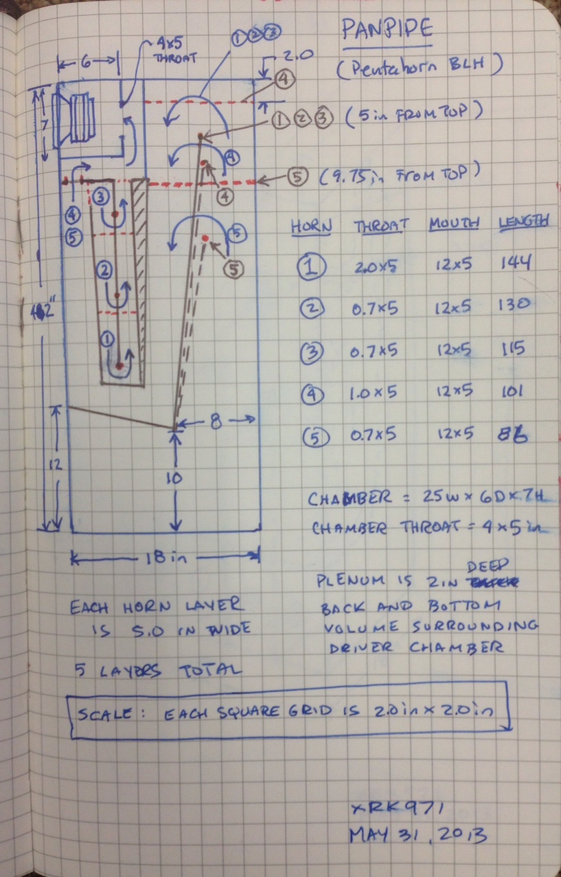
It was drawn in 3d by Another member:

The sims were in AkAbak so I did them all together - not separately. Responses simulated looked like this, not particularly pretty.
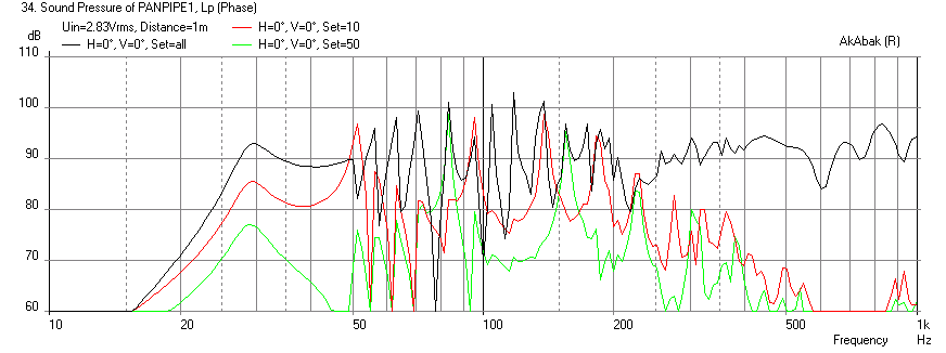
This was done back when I was new to AkAbak and designing BLH's. If I were to start from scratch, it would probably look better.
The closest thing is the Cornu, and I have measured the impedance at some point and it matches the sims. It was long ago and not sure if I have the measurement data anymore. The Cornu has two different lengths and emanates from a common throat. My Akabak sim matches the results obtained using a comprehensive 3d FEA model in Comsol Multiphysics done by another member. I trust the Akabak sim given this corroboration from both impedance measurement and another model.
I can find 2 sims:
http://www.diyaudio.com/forums/full...-spiral-horn-now-you-can-149.html#post3871894
http://www.diyaudio.com/forums/full...-spiral-horn-now-you-can-150.html#post3872084
But those are not that different compared to single TLs. I'm still not sure if Akabak can handle much more complex conditions..(your massive pipes🙄)
The 3d FEA model sim of the Cornu is here: http://www.diyaudio.com/forums/full-range/225622-ever-think-building-cornu-spiral-horn-now-you-can-149.html#post3871894
My model of the Cornu in AkAbak has 4 separate exit horns connected to two throats. AkAbak can handle up to 52 nodes, each waveguide or duct segment is 2 nodes and nodes can be shared. You can connect nodes at any node not just the ends so it can handle pretty complex geometries including bifurcations, feedback loops, etc.
My model of the Cornu in AkAbak has 4 separate exit horns connected to two throats. AkAbak can handle up to 52 nodes, each waveguide or duct segment is 2 nodes and nodes can be shared. You can connect nodes at any node not just the ends so it can handle pretty complex geometries including bifurcations, feedback loops, etc.
My own efforts analysing similar arrangements indicate that even when you balance the amount of energy into each duct, the output combines in a fairly chaotic way. The problem is that you have to take phase into consideration as well as amplitude. For example, if you have ducts resonant at 30 Hz and 50 Hz, you might expect to get a resultant response with peaks at 30 and 50 Hz. But the output of the "50 Hz" duct at 30 Hz might be out of phase with the "30 Hz" duct, resulting in partial cancellation of the 30 Hz.
- Status
- Not open for further replies.
- Home
- Loudspeakers
- Full Range
- Dual/Triple tuning TL/Horn: bad idea?