Would using an ECC83/12AX7 family double triode as a stereo pre-amp driver cause much, if any, cross-channel interference?
Similar question for using a 6AS7G double power triode?
I'm curious to experiment and see if a stereo single-ended amp could be made using just two valves (tubes).
Anyone tried this before?
Many thanks in advance.
Similar question for using a 6AS7G double power triode?
I'm curious to experiment and see if a stereo single-ended amp could be made using just two valves (tubes).
Anyone tried this before?
Many thanks in advance.
Member
Joined 2009
Paid Member

Many audio companies have shared dual triodes between channels in audio preamps.
Sounds like an interesting project, keep posting here.
Sounds like an interesting project, keep posting here.
It would be useful to realize that a stereo system does not require more than some 30...35 dB crosstalk attenuation. Many hi-end MM- and MC cartridges have only 25 dB.
It is possible, no problem in general, but for 6AS7G some 250 Vpp low distortion drive voltage is needed.I'm curious to experiment and see if a stereo single-ended amp could be made using just two valves (tubes).
Thanks for the link - the schematic is a little blurry, however I've found clearer examples by using Liliput Valve Amplifier as the search term. It's a shame the quoted power output is so low at 2.5w, I was hoping to get around 5w per channel.
It's given me a great starting point - so thanks for the help 🙂
As mentioned above, you shouldn´t have any problem; layout, grounding and shielding will still be big factors avoiding crosstalk, but if you wish, I suggest instead of a 12A*7 , you use instead a very high quality ECC88, 6N2P, etc, which have "6.3Vac only" filaments, prewired from pin 4 to 5 (instead of dual voltage 12A*7 which uses 3 pins).Would using an ECC83/12AX7 family double triode as a stereo pre-amp driver cause much, if any, cross-channel interference?
This not only liberates pin 9 but more important, they added a screen/internal shield between triode sections, grounded through pin 9 ... what the Doctor ordered 😉

Thanks - I have a "large collection" of 6N2P-EV. To drive the 6AS7G with sufficient voltage swing I was thinking about 6N1P-EV since that can take a higher B+ voltage. I appreciate the gain is significantly lower compared with 6N2P, so that's another factor.As mentioned above, you shouldn´t have any problem; layout, grounding and shielding will still be big factors avoiding crosstalk, but if you wish, I suggest instead of a 12A*7 , you use instead a very high quality ECC88, 6N2P, etc, which have "6.3Vac only" filaments, prewired from pin 4 to 5 (instead of dual voltage 12A*7 which uses 3 pins).
This not only liberates pin 9 but more important, they added a screen/internal shield between triode sections, grounded through pin 9 ... what the Doctor ordered 😉

Don´t overthink it, any of them will give you more than enough output signal 🙂
Thank you very much. That's prefect, much appreciated.
Nice little amp.
Somewhat worried schematic does not show any filament reference to ground: neither center tap nor resistive artificial one.
Not even (ugh!) grounding one end of winding.
Nor do they tell builder to ground pin 9.
Somewhat worried schematic does not show any filament reference to ground: neither center tap nor resistive artificial one.
Not even (ugh!) grounding one end of winding.
Nor do they tell builder to ground pin 9.
I've found this version.... still no grounded pin 9 though.Nice little amp.
Somewhat worried schematic does not show any filament reference to ground: neither center tap nor resistive artificial one.
Not even (ugh!) grounding one end of winding.
Nor do they tell builder to ground pin 9.
Maybe designer thinks "it´s widely known, no need to write it"
Me? ... I prefer to play it safe and not assume details are unimportant.
Me? ... I prefer to play it safe and not assume details are unimportant.
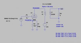
You can get 4.5...5 W from one half of 6AS7G, but this require optimum operating conditions, which are about as follows:It's a shame the quoted power output is so low at 2.5w, I was hoping to get around 5w per channel.
- Ua = 250 V (= some 370...380 V as +Ub)
- Ia = 50 mA
- Rload = 2k5 to 3k5 (see attached sim.)
- Ug(ac) = some 250 Vpp
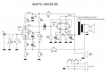
I have done 6AS7G SE amplifier, but used one tube (two halves) as the output stage. Power output was some 9 W. Attached my schematic too.
Attachments

- Home
- Amplifiers
- Tubes / Valves
- Dual Triode crossover