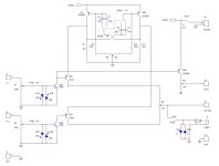
First impressions: unorthodox drawing style, Ic-q2 is summing of only base currents from q2 and... another q2? There are six q2's!. How to calibrate the attenuators and the separation pots? Purpose of S2? Frequency range with R9? Assume that all connectors shown are banana-style - BNC is preferred. Other issues pending.
Thank you
It is more modern.
On paper it should work great.
The best I can test is 5 MHZ but it could go as high as 250MHZ.
Most that would build would any only has a cellphone witch is only 40 KHz.
Thank you for your work.
Dave
It is more modern.
On paper it should work great.
The best I can test is 5 MHZ but it could go as high as 250MHZ.
Most that would build would any only has a cellphone witch is only 40 KHz.
Thank you for your work.
Dave
Your schematic is great.A more traditional view (no suggested modifications, back annotated with capitals).
My last project was a VTVM using a chip instead of a tube and from command parts. But did take months to work out little problems.
All parts was purchased from Amazon or Walmart.
This is simpler it just switching signals.
Adding the cellphone to switch will help anyone that does buy a Oscilloscope
The switching rate can as little as 20Hz to way over 10KHz.
At 10KHz give somther view compared to 5KHz. At 20Hz give two different views.
FYI
You do not need to use the SNYC it only option and is not found on cellphone apps.
I use my Eico 488 all time not using the SNYC.
Dave
You do not need to use the SNYC it only option and is not found on cellphone apps.
I use my Eico 488 all time not using the SNYC.
Dave
Here last project I didA more traditional view (no suggested modifications, back annotated with capitals).
Here my last finished project.A more traditional view (no suggested modifications, back annotated with capitals).
A VTVM using a chip
The file has a photo and schematic
Attachments
If Q2A is ever turned on it will fry along with Q2E. That's probably not what you want...
Instead of the multiplexing, why not just use the L and R channels of the phone and the two channels of the scope?
Tom
40 kHz on a cellphone?? That would surprise me. POTS was limited to 4 kHz as I recall. Same for GSM as I recall. I would expect the microphone to be sampled at 44.1 kHz or 48 kHz at the most. I'm willing to be proven wrong, though. 🙂Most that would build would any only has a cellphone witch is only 40 KHz.
Instead of the multiplexing, why not just use the L and R channels of the phone and the two channels of the scope?
Tom
It does need resistor for protection. Witch I did not show.
There few others I need add for protection too.
Thank you
Dave
There few others I need add for protection too.
Thank you
Dave
There are a lot cellphones only have one channel.If Q2A is ever turned on it will fry along with Q2E. That's probably not what you want...
40 kHz on a cellphone?? That would surprise me. POTS was limited to 4 kHz as I recall. Same for GSM as I recall. I would expect the microphone to be sampled at 44.1 kHz or 48 kHz at the most. I'm willing to be proven wrong, though. 🙂
Instead of the multiplexing, why not just use the L and R channels of the phone and the two channels of the scope?
Tom
Dave
Ah. Good point.
Now going back to your circuit: One idea could be to make the two inputs differential and switch the current source for the diff pairs back/forth. I've done that in the past and it worked pretty well. Another option could be to use transmission gate switches, such as the 4066 CMOS analog switch.
Tom
Here more update schematic showing resistors to protect the transistors from overloagood luck, instead of my deleted former entry here
the mods know
Attachments
Referring to my drawing in #6, Q2C and Q2D are in deep trouble.
Q2A and Q2B are very sad. The illustration in #9 is deluding.
Despite the added resistors, this design has a very high AI-level.
Worse then any copypaste I've seen, ever.
Q2A and Q2B are very sad. The illustration in #9 is deluding.
Despite the added resistors, this design has a very high AI-level.
Worse then any copypaste I've seen, ever.
My last project had ups and downs too.Referring to my drawing in #6, Q2C and Q2D are in deep trouble.
Q2A and Q2B are very sad. The illustration in #9 is deluding.
Despite the added resistors, this design has a very high AI-level.
Worse then any copypaste I've seen, ever.
the mods know
It is a simple amp and switch combo.
If look the old tube type they used very few parts and is a just a amp and switch
Dave
- Home
- Design & Build
- Equipment & Tools
- Dual trace build for oscilloscope and cellphones
