Any problem with setting two toroid transformers closely side by side? In close proximity to the two amp driver boards?
I have a rather rare Rotel RA-1412 integrated amp (110WPC), with a missing transformer. The unit uses separate power supplies for each channel, with a separate transformer (43-0-43, unknown VA rating). The channel with the missing transformer works, as I had a 35-0-35 transformer sitting around and connected it to see if the channel was operational.
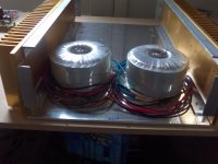
So, to straighten this out, I thought of removing the remaining EI-core transformer and replacing it (and the missing transformer) with a pair of Plitron 300VA 40-0-40 transformers. I can just squeeze them into the available space, side by side. Not enough room to put one on top of the other, as I have seen others do with toroids.
Feasible? Or is there a possibility of interference of one with the other, or with the toroids interfering with the driver boards causing hum?
Thanks gentlemen...
I have a rather rare Rotel RA-1412 integrated amp (110WPC), with a missing transformer. The unit uses separate power supplies for each channel, with a separate transformer (43-0-43, unknown VA rating). The channel with the missing transformer works, as I had a 35-0-35 transformer sitting around and connected it to see if the channel was operational.
So, to straighten this out, I thought of removing the remaining EI-core transformer and replacing it (and the missing transformer) with a pair of Plitron 300VA 40-0-40 transformers. I can just squeeze them into the available space, side by side. Not enough room to put one on top of the other, as I have seen others do with toroids.
Feasible? Or is there a possibility of interference of one with the other, or with the toroids interfering with the driver boards causing hum?
Thanks gentlemen...
One important characteristic of a toroid transformer is its lack of external field and its insensitivity to external fields. So you can probably mount them any way you like.
Depends on placement. Do not mount them axially on the same axis. The radiated field is NOT negligible.
As I said, the only way to fit them in is to mount them side by side.
View from above: -> OO <-
😉
View from above: -> OO <-
😉
Any problem with setting two toroid transformers closely side by side?
Do not mount them axially on the same axis.
I built a dual mono PSU with two large toroids on the same axis and don't see any particular problems. In fact I have the worst case scenario, two magnetically shielded (even more magnetic field along axis) in rather close proximity (less than 10cm) to the VAS.
With a little mu-metal and optimised wiring, no humm. Spectrum analyzer says humm is about 80dB below 0.7V (gives more than 100dB dynamic range for ~90W amp).
I get about the same numbers with only a single toroid in place.
Interestingly, I got about the same result with a single R-core mounted in the same position, which I think is fairly good for a R-core.
In close proximity to the two amp driver boards?
Depends on exact situation, including sensitivity of your speakers, how far you sit away from them and how much humm annoys you.
I guess not much of a problem as the drivers do not have gain, the real problem starts when humm enters voltage gain stages as it gets amplified.
Have fun, Hannes
By 'driver boards', I mean everything it takes to boost a line-level signal to drive an 8 ohm speaker to 100W levels. Diff-pairs, VAS, driver, outputs. The toroids will be within 4cm of them.
I'm asking because the Plitron transformers cost about $100 each. If this fails, that's $200 I can kiss goodbye to. I do not want to fool with MU-metal, as I've never seen the stuff have any effect when trying to battle EMF issues. Yeah, it's supposed to. Maybe I'm doing it wrong, but if I have to play around with that junk I'd rather just part this thing out and not fool with it.
I'm asking because the Plitron transformers cost about $100 each. If this fails, that's $200 I can kiss goodbye to. I do not want to fool with MU-metal, as I've never seen the stuff have any effect when trying to battle EMF issues. Yeah, it's supposed to. Maybe I'm doing it wrong, but if I have to play around with that junk I'd rather just part this thing out and not fool with it.
Yeah, 4cm to VAS is really close, you should definitely expect humm.
Of course that also depends a bit on bias, for ClassAB current draw is light, so is magnetic field (in comparison to high bias ClassA or so). But still it's likely a problem.
I have no idea how you could get around that problem, maybe with an external power supply. SMPS emit at other frequencies, maybe also an option.
By the way, mu-metal works ok (6-10dB damping if I remember correctly), it's not a wonder material. It cannot really shield the magnetic field in most cases (except for 100% encapsulation), that's the nature of magnetism. It redirects the field, something to keep in mind when working with this stuff.
Have fun, Hannes
Why then were the original transformers able to be mounted so close to the driver boards, when they are supposed to be so leaky with EMF? If the toroid has so much less leakage, wouldn't it be an improvement over the stock units?
Locate the input circuits. I bet they are far enough from the transformers.
I think it would.wouldn't it be an improvement over the stock units?
Last edited:
Well, I missed this is about a commercial amp.
I guess the EI's were mounted optimally oriented such that the emitted field is lowest in direction of sensitive circuitry.
2nd, that's very likely a ClassB amp, so idle currents are low and the EIs emit only a small field. I was told toroids emit more magnetic stray field at low currents in comparison to EIs. I don't know if that's true as I don't have much experience with EIs.
Anyway, I would recommend to use the smallest toroids that you feel ok with. Peak current capability is anyway much above continous rating of the transformers.
Have fun, Hannes
Mounting toroids in this fashion can be optimized depending on AC phasing. You can set up one to buck the stray field of the other. Side by side mounting is not optimal for this, one on top of the other is much better, sadly you don't have that option.
Toroids generally have lower stray fields if correctly dimensioned. For instance, DO NOT use halogen lighting step-down toroid transformers with rectifiers and capacitor filtering - these are NOT correctly dimensioned regarding maximum field strength for such a thing - they expect a resistive load so current has a sinusoidal waveform and the whole setup has a very high power factor. This is nothing like a typical power supply in an amp.
From the example given, you can infer that transformers of any kind, intended for use in a capacitor filtered rectifier setup, can only be properly dimensioned if the components in the power supply, most importantly diodes and filter caps, are known in advance. Transformers for such a purpose are wound with a much lower field density because the current through the windings only flows at the peak of the mains AC sinewave, when the secondary voltage is more than that of the capacitors plus rectifier diode drops. The current is roughly half-sine shaped, the period is dependant on the cap size, it's ESR, ESL, the transformer stray inductance and diode internal resitance (disregarding for the moment diode recovery effects) and is many times larger than the mean current drawn from the power supply. Because of this peak nature of the current, it is relatively easy to find a combination of components that will saturate the core of the transformer, at which point the magnetic field escapes it and becomes a 'stray field' and a huge one at that.
Because toroid cores have no gap, they saturate very abruptly and hard. Because their stray inductance tends to be very low (because of excellent primary to secondary inductive soupling) and the amount of wire is optimized in length, the peak currents are very high compared to equal rating EI or C core transformers. The pulses are shorter and taller, resulting in much more EMI and RFI when the core saturates. In other words, a toroidal transformer is FAR less forgiving with respect to incorrect PSU design.
There are three general strategies when it comes to picking a correct toroid transformer for a simple PSU:
1) The transformer is custom wound for a lower field density. IF the winder does not alow you to specify this, you can get around the problem by specifying a higher voltages, keeping the voltage ratios the same. For instance you could specify a 160VAC primary intending to use it on 115VAC, and get roughly 2/3 of the power rating for a given core. This is exactly what would happen if you specified lower field density - the core needs to be larger for a given VA rating in order to keep the field density lower.
2) Intentionally specify lower regulation, i.e. higher losses and thinner wire in order to increase the internal resistance of the windings, thereby limiting the amplitude of the current peak. To an extent you get this by specifying higher voltages keeping ratios the same as the winder will automatically adjust currents lower for the given VA rating and use thinner wire. There are more windings per volt so the wire is longer, resulting in higher resitance. However, here I am refering to the practise of slightly underdimensioning the secondary winding wire thickness. Primary is usually kept the same especially if there are other auxiliary windings you wish to have better regulation. This strategy works well in class AB amplifiers because the peakt o mean power ratio is so high - you could seriously underdimension the wire and still get very adequate performance with music signals. Test sines would however reveal a low regulation transformer and possibly overheat it if alowed to work at maximum power for prolonged periods of time. In cases like the one in this thread, series resistors can be added to the secondary to test if an observed excessive stray field is in fact due to transformer saturation due to improperly dimensioned transformer or filter caps. 0.1-0.22 ohms in series with each side will be adequate - these actually produce much more of a current drop than one would expect (keep that in mind when dimensioning them). Another way to test this is to put a (larger) resistor in series with the primary. This test will also reveal EMI/RFI and ringing associated with rectifier diode recovery.
3) Use a higher VA rating transformer. This strategy is about the only one you can use if you have no winding data for the transformer except the VA rating and voltages. If so, heavily overdimensioning the transformer is about the only strategy you can use for something like a class A amplifier where the power supply always gives the same, maximum power (or close to it). Another case where this might be necessary is when very large filter caps are used.
Simulators can be very useful when checking a design, assuming you can measure the transformer's characteristics. A RLC meter will do the trick. You need to measure primary and secondary resistance (when measuring one, keep the other windings shorted) and stray inductance (form secondary, measured with primary shorted). Transform the resistance of the primary by dividing with 1/(n^2) to put all lumped components into the secondary circuit. Use an ideal generator with the same voltage as the unloaded secondary, in series with all resistances and inductances as a crude model of the transformer. Check peak currents against transformer specs - you might be surprised.
You're making the assumption that I have the transformers here to play with, or that I have a number of transformers to choose from, or even that the budget for this project is such that I could have one custom made. I wish... 😉
The only transformers I have found that would work are the Plitron 40-0-40 300VA units (there is a 225VA model with the same secondary voltage). The cost of finding out if they would work is over $200. They cannot be mounted one on top of the other, as I only have 4" to work with (each 300VA transformer is 2.25" tall). The phasing idea is something I had not thought of, but as you say, it works best with stacked units, not side-by-side.
The owner, a friend of mine, is not too keen on throwing away $200+ for a project that isn't going to work out. And while your explanation is very good, I essentially have only one transformer to choose from, and only one way to mount them...side by side, and closely at that. So if there's a good chance that I'm going to end up with a humming, buzzing mess, then this Rotel is going into the 'never-to-be-repaired' pile.
In this case you have to rely on strategy #3 and also on the option that you can call Plitron support and ask them a few relevant questions - like winding resistances and such, if not what calsulation they used todesign the transformer, such as what kind of smoothing cap it's designed for. You also have one original transformer to measure and compare with. Other than that, if the plitrons are wound properly (and there is really no reason they should not be), so you don't run into saturation problems, there is no reason to expect any more hum than there was with the original units.
I have run into your problem a number of times, and the solutions to it were varying - if I can, I custom-wind transformers, which is actually amazingly easy to do in this country, in theory. There are a lot of winders but unfotunately not many know how to properly calculate what is to be wound, so I use the strategies above. However, sometimes this becomes too expensive or they just won't do something that is so highly customized (for instance, they may have cores with pre-wound primaries and only wind secondaries to order). Then it's back to your problem.
The solution is then a combination of strategy #3 and some extra stuff.
Generally, like in your case, find the largest toroid that would fit, except in the case where I can get some relevant data, like winding resistance.
If I have the original transformer, even if it has a shorted winding or something like that, it can give me a lot of good data. For instance, if you measure the approximate cross section of the core inside the winding bobbin - this is normally easy because the central leg of the E shaped lamination has the same width as the two outer legs combined - in cm square, you can get the approximate VA rating by multiplying with 0.9 and then squaring the result. This assumes about 9000 Gauss (0.9T) field density, which is the norm for standard EI laminations.
If you have some good windings to measure the resistances of, you can calculate the regulation the transformer was designed for. For instance, for a 115VAC to 43-0-43VAC = 86VCT transformer, take primary resistance and multiply by (86/115)^2 then add to the resistance accross the 86VCT winding. Take approximate VA rating calculated from core cross-section and divide by 86V (unloaded secondary voltage) to get maximum current, then multiply this current by the resistance sum from previous section - this gives you the internal voltage drop of the transformer. Subtract this from the unloaded voltage to get fully loaded voltage - keep in mind this is for a resistive load.
If you can measure inductances, you can also measure the stray inductance - this is useful if you wish to use the data calculated above to simulate the PSU, so you can see what ripple current the transformer was designed for. In some cases it's also possible to measure this current using a simple DVM (NOT true RMS as you want peak values), but the internal shunt will limit the current peaks, so you will see a smaller value. Still, it might be good enough as a reference. You can also use an external shunt (say 0.1 ohm resistors, maybe 2 in paralel) and observe with a scope (careful, scope ground is usually earthed so returns to the ground fot he amplifier if the amplifier is grounded - you will need to lift the amp earth to do this).
When you have all this data, you can compare it against the new toroids.
Winding resistances will surely be lower with toroids, sometimes as low as 1/4 of the original. As a result, ripple current will be higher unless something is done to lower it. Wether this ripple current will produce saturation effects depends on how the transformer was designed. Even though the winding resistance may be 1/4 of that on the EI original, the ripple current will not be 4x higher but may - depending on wiring and diodes - easily be twice as high. Ask Plitron if their transformer will cope with that.
If you decide to risk it but run into problems, you can still 'simulate' the original transformer by inserting resistors in series with the windings (primary is best since this also provides a softer start unless you already implemented soft starting). To get the exact value, take the 86VCT original winding resistance and subtract the 80VCT winding resistance of the new transformer (assuming Plitron can tell you what it is in advance, or you decide to buy them anyway). Then multiply that by (115/80)^2. add this to the difference of original and replacement primary winding resistance. This gives you a primary series resistor that will simulate the winding resistances and regulation of the original transformer, using the replacement. Use a high power rating - at full power this will dissipate a lot of heat, perhaps as much as 20W, but it will only be a fraction with music signals.
Also you can implement a stray field short. This is the copper foil shorted winding on EI transformers that goes around the outside circumference of the whole core around the bobin. You can do the same for a toroid transformer by enclosing it into a metal box (careful not to end up with a shorted winding by alowing the mounting screw to connect the box top and bottom through the center hole of the core!!!). It is often not necessary to do a full enclosure - a few bands of copper foil around the core avoiding the mounting screw, will do wonders. HOWEVER - keep in mind that if the toroid is wound properly and is operating properly (no saturation) you should not need this, setting up the two transformers to buck each others stray field should do just fine even if they are side by side.
And also - why not initially order ONE transformer? Prehaps even the 225VA version if you want to lower shipping on account of the lower weight. This will lower the risk by lowering the price, and even if you end up with one extra 225VA transformer, it's not a useless item. If it works out, however, you can always either order another one, or return that one as a wrong order 🙂 and have it replaced with additional payment, for two 300VA units.
I have just recently repaired a Rotel 1062 amp where the toroid is mounted right next to the left channel power amp, perhaps 8cm away from the driver board. It only has a rather flimsy aluminium cover cap, not a full enclosure or potting so it's acting as an ornament only, and not as a stray field short. The filter caps are 2x10000uF (it's a 60WPC amp) but it is wound with thinner wire (I estimate it's a 160-180VA unit, comparing to some I have custom wound here, the secondary wires have about 1/2 the cross section). No problems with stray field at all...
Last edited:
110W per channel into 8r0.
That is possible with a 35Vac+35Vac transformer. I get 110W to 120W from 35Vac and ~200W into 4r0. 40+40 gives me ~170W into 8r0.
40V+40V and 300VA+300VA may be too stiff a PSU and too high a voltage under heavy loading and take the outputs and/or drivers beyond SOAR.
That is possible with a 35Vac+35Vac transformer. I get 110W to 120W from 35Vac and ~200W into 4r0. 40+40 gives me ~170W into 8r0.
40V+40V and 300VA+300VA may be too stiff a PSU and too high a voltage under heavy loading and take the outputs and/or drivers beyond SOAR.
This is a good point, and in fact suggests that the original is a low regulation transformer - which is commonly and purposefully done commercially to give an amp high peak power but limit current in case of prolonged demand in order to save the outputs. This sort of setup comes with large smoothing caps. With a stiffer transformer, you get roughly the same thing by reducing the capacitance of the smoothing caps, which incidentally lowers ripple current. However, it has other repercussions, including that it 'doesn't look good - is not fashionable'.
That being said, using a lower voltage, higher current part will actually make the PSU stiffer but the lower voltage will free a bit of SOA.
That being said, using a lower voltage, higher current part will actually make the PSU stiffer but the lower voltage will free a bit of SOA.
Last edited:
I would be very tempted to try a 4secondary 35Vac toroid about 400VA to 600VA.
This will get the 100W+110W and keep the two channels isolated from each other until it is commoned inside the amp chassis.
BTW, a 2secondary 60Vac or 70Vac can be split to get 4secondaries @ 30Vac or 35Vac.
The lower voltage version just needs a few dozen turns of enameled wire to get the 35V needed.
I've tried doing that on one single secondary 70VAC - installing a CT. It is possible but it's a PITA. Depends highly on how the transformer is wound, sometimes it's not easy to dig out the proper point on the wiring for the center tap. On mine it was done in 3 passes around the core, probably due to the wire thickness. The fact that the center was full of resin so a retainer nut can be installed, made thing quite difficult. I imagine doing that for a dual secondary may prove even worse even though duals are usually bifilar wound so in theory the two wires always go in parallel.... With CT windings it's really imperative to keep them truly center tapped - equal voltages and resistances of the winding halves - otherwise a DC field component will occur in the core due to the imbalance between mains AC half-periods. As has been stated many times, such a component very easily saturates the core of a toroidal transformer, so we are back to stray fields due to saturation. It's a better idea to find the CT point and actually snip the wire and thus create two extra ends for two separated windings. Then, rectify each with a full wave bridge and although the voltages may end up slightly imbalanced, there will be no net DC field in the core.
The amp currently has a mishmash of different output devices, and if the unit is to be trusted to work properly and if I go forward, the outputs will get replaced with MJ21194G's (quasi-complementary amp).40V+40V and 300VA+300VA may be too stiff a PSU and too high a voltage under heavy loading and take the outputs and/or drivers beyond SOAR.
- Status
- Not open for further replies.
- Home
- Amplifiers
- Solid State
- Dual Toroids in Close Proximity...An Issue?