Hello people there. I've just bought the stuff neccesary to assemble two LM1875 split suply and fit a stereo amp. I got evr'ything but the supply.
I guess I need a dual supply, but I have no idea about how to assemble it. I can't find any diagrams of it, and I know that supply is the most important thing to make an amp work.
I'll use two 10W speakers, so I guess the source has to be a +20/-20 V, 1A, but nothing else.
Has anyone fitted that kind of supply for the LM1875? Can you show me diagrams, datasheets, pictures or whatever?
Tank you very much,
Alexis.
Here it is:
The image is linked from http://sound.westhost.com/project72.htm , where a LM1875 based amplifier is described.
Did you think something like that?
An externally hosted image should be here but it was not working when we last tested it.
The image is linked from http://sound.westhost.com/project72.htm , where a LM1875 based amplifier is described.
Did you think something like that?
Be careful at the primary side of the transformer! There are lethal voltages, that can kill you in a moment, if you touch at the wrong part!!
Also be areful at the secondary-side. 20-30V is not as dangerous as 230V, but touching a capacitor, charged to 25V could be "surprise".
Good luck on the project!
Also be areful at the secondary-side. 20-30V is not as dangerous as 230V, but touching a capacitor, charged to 25V could be "surprise".
Good luck on the project!
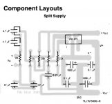
The PCB for split provided by National in the datasheet of LM1875 has a mistake, there's a 1000 uF cap with not specified position. Should I put - in the V- track?
The one I'm reffering to is bellow the chip in the picture:
http://petrovich.nutus.com.ar/Split supply corregido.jpg
Also, I made a new PCB with Photoshop, fited to a 36x36 holes multi-purpose grid. It will be here in next post, availabe for whose don't want to print a special PCB (which can be a little expensive in some countries).
Alexis
Hi,
a 15Vac + 15Vac 50VA transformer will give about +-20Vdc and sufficient power for two channels with maximum power between 10W and 15W/channel.
Use +-10mF on each amplifier's supply rails.
Your smoothing caps could be right on the limit @ 25Vdc. I would use 40Vdc to allow for higher than normal mains voltages.
Hi dovganj,
Yes, I have corrected your picture.
dovganj said:The PCB for split provided by National in the datasheet of LM1875 has a mistake, there's a 1000 uF cap with not specified position. Should I put - in the V- track?
The one I'm reffering to is bellow the chip in the picture:
http://petrovich.nutus.com.ar/Split supply corregido.jpg
Alexis
Yes, I have corrected your picture.
Attachments
Hey, Anders... I've just finished one channel and tested it. The cap I was refering to got burned..., set as you said.
In addition, the chip got very hot and shuts down, so I guess that the heat sink is indispensable.
As final thing, the audio out has too much distortion, so, what are critical components to reduce it?
Thank you.
Alexis
In addition, the chip got very hot and shuts down, so I guess that the heat sink is indispensable.
As final thing, the audio out has too much distortion, so, what are critical components to reduce it?
Thank you.
Alexis
Well, here there's the amp PCB corrected from the datasheet and fixed to a 36x36 holes multipurpouse grid :
and the supply diagram:
The circuit I made is exactly as in the picture, except the 20k resistor, which is a 22k cause I forgot buying the rigth one.
Respect to the supply, I've just noticed that the out delivers 2.5A, what is too much (the tester extremes spark when I touch them).
I thik I should reduce current, ev'rything else is OK.
Any suggestion?
Thank you,
Alexis.
An externally hosted image should be here but it was not working when we last tested it.
and the supply diagram:
An externally hosted image should be here but it was not working when we last tested it.
The circuit I made is exactly as in the picture, except the 20k resistor, which is a 22k cause I forgot buying the rigth one.
Respect to the supply, I've just noticed that the out delivers 2.5A, what is too much (the tester extremes spark when I touch them).
I thik I should reduce current, ev'rything else is OK.
Any suggestion?
Thank you,
Alexis.
Hi,
you should not reduce the peak current ability of the PSU.
the Hi current only flows if the amplifier/load demands it.
10W into 8ohms needs a fair current to operate properly.
10W is equivalent to 12.6Vpk.
Peak transient current into a difficult 8ohm speaker is 12.6/8/0.35<=4.5Apk.
BTW,
your DMM probes should not spark. What are you doing wrong?
dovganj said:I'll change the chip for a new one, and I'll place new 1000 uF caps, 35V ( I was using 16V ones).
Also, I'll replace supply diodes. I was using 1A, I'll use 3A.
Last item, I'll ensure that heat sinks are properly placed before a new test.
Wish me succes, goodbye.
Alexis.
That's all over and done. The ciurcuit is checked and should be working, but I just got noise in the speakers.
I'm so sorry for my ignorance ( I'm just asking, and asking, and sometimes I don't even understand what I read); by the way, what's next?

- Status
- This old topic is closed. If you want to reopen this topic, contact a moderator using the "Report Post" button.
- Home
- Amplifiers
- Power Supplies
- Dual supply for LM1875 split supply