Hi!
Conditions to simulate, adjust and validate your circuit:
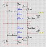
1. Instead of a DC source, use 2 x AC 60Hz sources with the rectifiers diodes. You will simulate the transformer.
Add series resistances to the sources according to the transformer you plan to use.
This way, you'll be able to evaluate the ripple voltage on several points of your circuit, including the output.
In order to ***** the series resistance, if you have the transformer, you can measure unload and load conditions and calculate the equivalent series resistance.
You can also measure the primary and secondary resistance. Reflect primary resistance to secondary by the transformer ratio.
If you don't have the transformer yet, you can take it's nominal current and assume that, for the load condition, voltage will drop around 10 to 15%, so you can estimate the serie resistance.
2. Add a load proportional to the average current your amp will drain. Take maximum amp power and for the rail voltage, estimate a resistance to load your power supply.
Voltages will drop at the transistor collectors and also in the resistor/zener network (transistor base).
You need to make sure the zeners don't go to zero current condition, when you loose the reference and voltage will no longer be stabilized.
3. Simulate the inrush current that will occur on the output transistors due to the 1000uF connected to the emitters.
You can do this by adding a switch to the AC source. Turn it when the 60Hz sinewave is at it's maximum (worst case).
You need to make sure you don't exceed maximum IC current and also the SOA during the time it will take to charge the capacitors.
Hoila Lineup,
I like simplistic voltage regulator, it's kind of classic and probably does the job for almost all aplications.
2 things to consider, just as I'm preparing similar regulator from battery 18-22v to opamp 15v for mc preamp:
1. Vref could be lower noise with array of selected leds instead of zener?
2. Output transistors can be ultra low noise ztx851/951 alone if power dissipation allows, if higher dissipation is required than these ztx can be darlington drivers for some to220 packed transistors..
What do you think?
I think this is a darn simple and nice regulated power supply. I would add 100nF ceramic capacitor across C1, C2 but certainly C3. These capacitors are so large they do have inductance.
Don't expect long-term mV accuracy. Both the 20 mA current thru the diodes and environmental temperature will influence diode voltage as well as Ube of the transistors. This is not a feedback circuit. For purposes of powering an amplifier this is totally adequate.
2x18V 1A transformer is too low. You loose another 1.5V-1.8V in the bridge rectifier. If you need 20V stabilized, then you need a 22V RMS transformer. Transfomers especially small transformers (50VA still is small) have significant deviation from the nominal voltage when unloaded. 22V is hard to get, so it would be either 20V or 24V. If you choose 24V the voltage regulation will be fine, but the transistor dissipation needs serious attention.
