I have an XLR input going into two transformers which is then creating two unbalanced and separate outputs. In order to have a separate ground lift on each, I think that it's fine to have switches (to make/break the ground connection) from the Sleeve of each unbalanced output to XLR Input Pin 1. It seems funny to remove the Ground on an unbalanced connection but with other commercial Reamps that I've seen the Sleeve is disconnected from Pin 1 so technically it should be the same concept.
Could you please clarify the question a little more?
Or, maybe what you are looking for can be found in something like: https://www.jensen-transformers.com/wp-content/uploads/2014/08/Audio-Transformers-Chapter.pdf
...Or, maybe in: https://www.jensen-transformers.com/wp-content/uploads/2014/08/generic-seminar.pdf
Or, maybe what you are looking for can be found in something like: https://www.jensen-transformers.com/wp-content/uploads/2014/08/Audio-Transformers-Chapter.pdf
...Or, maybe in: https://www.jensen-transformers.com/wp-content/uploads/2014/08/generic-seminar.pdf
+1 a block diagram would be useful showing chassis connections plus actual ground connections and I am assuming the transformer feeds 2 preamplifier sections as the outputs are unbalanced .
Thank you for the sources you provided!
The following block diagram is what I am trying to re-create i.e. one balanced input is split into two unbalanced outputs. From online sources I read that the proper way to convert from balanced to unbalanced is to not reconnect pin 1 to the sleeve of the output. i.e. leave the output entirely isolated to be connected to the guitar amplifier then.

Now my question is this. Many commercial reamps include the option to connect/disconnect the ground i.e. a Ground Lift Switch. In my case, would it be sensible (or useful) to recreate the ground lift switches by adding two separate ground lift switches to connect/disconnect the Chassis Ground (and Pin 1 Input) to either of the output sleeves? I have sketched these in red.
The following block diagram is what I am trying to re-create i.e. one balanced input is split into two unbalanced outputs. From online sources I read that the proper way to convert from balanced to unbalanced is to not reconnect pin 1 to the sleeve of the output. i.e. leave the output entirely isolated to be connected to the guitar amplifier then.
Now my question is this. Many commercial reamps include the option to connect/disconnect the ground i.e. a Ground Lift Switch. In my case, would it be sensible (or useful) to recreate the ground lift switches by adding two separate ground lift switches to connect/disconnect the Chassis Ground (and Pin 1 Input) to either of the output sleeves? I have sketched these in red.
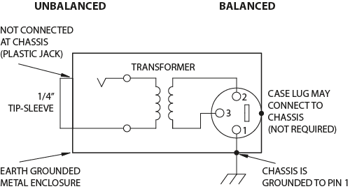
The outputs from the two transformers are balanced unless you connect one side to ground. I assume you mean you are driving unbalanced inputs from each of these transformers. The correct way to connect this is to not connect the unbalanced input's ground to the pin 1 ground of the source, like this schematic from Rane:
RANE Commercial - Knowledge Base
RANE Commercial - Knowledge Base
Last edited:
Hi @johnmath, I am driving a balanced input to convert it to an unbalanced output. I think that the same concept still applies no? See my reply above yours to further explain what I want to achieve.
In your schematic you can remove the red conductor and switch because they are not needed and will only introduce an earth loop and potentially hum if the switch is closed.
Have a read of the Rane sound system interconnection information linked:
RANE Commercial - Knowledge Base
Have a read of the Rane sound system interconnection information linked:
RANE Commercial - Knowledge Base
Hi John, I read your note and agree to be honest. However I am still confused as to why other commercial reamps (look at the Radial PRO-RMP for example) include the option to connect the ground (i.e. a ground lift switch). Perhaps this is an incorrect convention which caught on?
The outputs of your transformers are floating and can be connected to balanced or unbalance inputs. If you use a shielded unbalanced lead, the shield will ground one leg of the transformer making the connection unbalanced, but free of a noisy ground reference, and the shield will prevent noise being picked up on the other leg. You don't need to connect the pin 1 ground and it is preferable not to.
I see, the re-amper is a specialist tool used in an uncontrolled environment. There may be circumstances where the source being re-amped may benefit from an electrical ground.
For example, if the source is an unbalanced battery operated device, its screening may work better if connected to electrical earth through the re-amper. But most of the time this earth connection will degrade noise immunity, certainly with properly balanced sources.
It is not uncommon for low voltage devices to increase the available output signal voltage have push-pull (AKA bridged) outputs and they are often referred to as balanced, but in reality they are not truely balanced. I haven't thought through the implications of this type of connection but it probably is the same as above.
If you do want to keep the ability to connect the earth through, then what you proposed is perfectly fine.
Ok great then! Thanks John. As previously discussed I agree with the article from RANE but I wanted to build a unit which takes care of all the possible scenarios. One last question.
In the following diagram a (51Ohm + 10n) is used instead of an entirely open connection. Do you think that this method is 'safer'? Rather than a completely open ground connection.

In the following diagram a (51Ohm + 10n) is used instead of an entirely open connection. Do you think that this method is 'safer'? Rather than a completely open ground connection.
The point of the resistor and capacitor is to ground any high frequency noise without introducing an audible earth loop. The cutoff frequency for 51Ω and 10nF is 30kHz, which is above the audio range.
This circuit might help keep out strong RF signals that could become audible because of non-linearities in the audio circuitry. For example it may help keep out the buzzing interference from mobile phones.
The re-amp circuitry would normally be in a well screened metal box, however the cables going into and out of the box can act like antennae and feed RF signals into the screened enclosure. The RF bypass to ground is probably a good idea.
- Home
- Source & Line
- Analog Line Level
- Dual Reamp Output (Ground Lift Question)