I've built a lot of projects over the years, but this is the first time I've ever attempted to write anything resembling a "build thread". The main reason that I've decided to do so with this project is that this amplifier is rather unusual and might inspire others to do something similar. Also, it will probably be the last amp I ever build. First, some background (don't worry, pictures will follow in subsequent posts). . .
I've been building speakers for a long time, albeit not very prolifically. Over the years, I've developed the highest regard for the chosen few who know how to design great crossovers because, as a mechanical guy, this is something that I know I will never be able to do. This recognition was a severe constraint on my ability to design and build a pair of speakers from scratch - until I discovered digital signal processors and bought a miniDSP 4x10HD. If you're familiar with how these work, feel free to skip to my second post.
With the assistance of the excellent Room Equalization Wizard (REW) software and a microphone, my miniDSP allows me to measure the performance of speaker drivers and to build crossovers in the digital domain, which I can then use during the playback of music from a digital source. You still have to know the basics about what crossovers do and how they work, and you have to learn to use REW and a miniDSP, but it's a lot easier than designing and building passive crossovers using analogue electronics. However, there are some very significant differences between active digital crossovers and passive analogue ones.
For a conventional pair of speakers, you need a stereo amplifier so that you have two channels of output - one for each speaker. The analogue crossovers inside the speaker cabinet separate the incoming signal into two or more filtered frequency bands, each of which is directed to the appropriate driver.
In the case of the miniDSP 4x10HD, the digital crossovers do their filtering before the digital signal is converted to analogue and sent to the amplifier. This means that a two-channel amplifier is no longer sufficient - you need an amplifier with enough channels of amplification to deal with all the frequency bands that the digital crossovers produce. The 4x10HD is capable of producing eight channels of output - enough to supply a pair of 4-way speakers. How do you get so many channels of amplification? The easy way is to use a home theatre AVR that has multichannel inputs (originally intended for use with the analogue outputs from SACD or DVD-A sources).
My new speakers are 3-ways and each cabinet has a tweeter, a midrange, and a pair of woofers. With eight channels of amplification, I could drive each woofer individually in principle. Unfortunately, my AVR could produce only six channels of amplification, so I had to run each pair of woofers in parallel. This was not such a bad idea as it turned out.
Next: deciding how to power my new speakers.
My New Speakers
My new speakers with their miniDSP active crossovers and AVR amplification sound pretty good - better, in fact, than anything I have built previously - but they are not without their limitations. For example, you can't simply insert them in another system, because they need active crossovers and multichannel amplification. This makes it difficult to conduct an A/B test., although I can insert the AVR in another system and run it in stereo direct mode, so although I can't A/B my speakers with a single amplifier, I can A/B the amplification with a single pair of speakers.
I compared my AVR in stereo direct mode with my home-built AKSA 100N+ amplifier using the same digital source and DAC - the AKSA won. This alone wouldn't have been very helpful if I hadn't happened to have listened to Tom Christiansen's prototype Neurochrome Modulus-686 stereo amplifier a year earlier. I had done a similar A/B test between it and my AKSA - Tom's amp won. So now I had this constant niggle every time I listened to my new speakers powered by my multichannel Arcam AVR - no matter how wonderful they sounded, they would almost certainly sound better still driven by multiple channels of Neurochrome amplification. I had no choice but to build a multichannel Neurochrome amplifier. If you want to read up on Neurochrome amplifiers, look here: Build your own state-of-the-art audio amplifiers – Neurochrome Audio
Next: the design objectives for my new amplifier.
Amplifier Design Goals
I've already touched on a fairly serious limitation of multichannel systems with active digital crossovers - you can't run the speakers with a conventional stereo amplifier, because they lack passive crossovers. Similarly, I didn't want to spend a lot of time and money building a multichannel amplifier that I couldn't run with a pair of conventional speakers. I wanted enough flexibility to be able to configure the amplifier as either a multichannel amp or a conventional stereo amp, and I wanted to design the whole thing such that it would be easy to use by some future owner.
Here were my very simple design goals:
1. Able to drive my new loudspeakers via digital crossover outputs from a miniDSP 4x10HD. This is the fundamental purpose.
2. Able to drive a conventional pair of stereo loudspeakers that have passive crossovers. This speaks to the flexibility I want.
3. Have superb sound quality. I believe that all Tom's designs meet this criterion.
4. Use balanced XLR inputs. The miniDSP offers a choice of balanced and unbalanced outputs, so it would be foolish not to take advantage of the balanced outputs.
5. Use SpeakOn speaker outputs. With multichannel amplification, you end up with a lot of speaker cables, so it makes sense to use Neutrik SpeakOn multi-pole cables and connectors. They can be expensive, but you need only one terminated cable per speaker.
6. Isn't of overwhelming physical size and weight, and doesn't dim the lights when I turn it on. I'm married.
Next: other design considerations.
Design Considerations
I started off by assuming eight identical channels of amplification, because I had eight drivers in my speakers, the miniDSP has eight outputs, and, conveniently, there's an eight-pole SpeakOn cable and connector (there isn't a six-pole available). If I used eight of Tom's Modulus-86 amplifiers, I could run my dual woofers at 40 watts each or double up to 80 watts for a single woofer in some future speaker design. With some thoughtful switching, I could also reconfigure for use as a two-channel stereo amplifier with 4 x 40 Watts per channel.
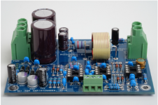
This a Modulus-86 amplifier (photograph used with permission):
I spent a lot of time working on the configuration of amplifier modules, power supplies, and transformers, and trying to fit them in a Dissipante chassis. Two things eventually became evident: first, eight channels would be really pushing my already out-of-control budget, and second, 40 Watts per woofer might be marginal. Time for a re-think.
I decided to use four Modulus-86 amplifiers to drive the tweeters and midranges as before, but now with two Modulus-686 amplifiers to drive the paired woofers. This would give me 40 Watts for each tweeter and midrange, but 130 Watts instead of 80 Watts for each pair of woofers. The clincher for this arrangement was that I could run the whole thing as a conventional two-channel stereo amplifier for speakers with passive crossovers by simply using only the woofer line inputs and speaker outputs. In other words, I could have a 130 Wpc stereo amplifier by using only the Modulus-686 amplifiers.
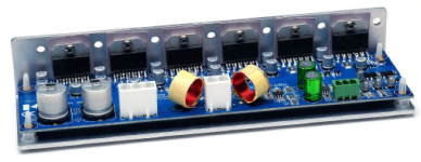
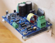
This is a Modulus-686 amplifier:
At one point, I was concerned whether a component failure anywhere in the system could result in an unattenuated signal reaching (and destroying) any of my drivers. I considered adding a Goldpoint six-channel stepped attenuator, but eventually decided against it; the attenuator would add a significant additional cost and such a component failure seems improbable. I already have volume controls on my Squeezebox and the miniDSP, but I have left room in my design to add an attenuator in the future if I change my mind. While I was debating this subject, I took a look at the gain structure of the system . . .
The midrange drivers in 3-way speakers nearly always have to be padded down, and mine are no exception. This is done in the miniDSP. Now, Tom's amplifier modules can be built with a choice of gains, so in my design it's a simple matter to reduce the gain of the midrange amplifier modules. With less gain from the midrange amp, I can reduce the attenuation of the mid provided by the miniDSP's filters by the same amount. Note that this doesn't affect the use of the unit as a conventional stereo amplifier, because only the woofer modules would be used in that application. Returning the midrange modules to their original gain for use with some future speakers would entail changing only one resistor in each module. If a catastrophic component failure were to happen, it would burn out the tweeters but the mids and woofers would probably stay within their excursion limits and thus survive. Probably . . .
The remaining design considerations revolved around thermal management, cable management, and just getting everything into the space available. I spent a long time roughing out numerous layouts in Sketchup before coming up with one that I was confident in. More on this in my next post.
Next: final design.
I started off by assuming eight identical channels of amplification, because I had eight drivers in my speakers, the miniDSP has eight outputs, and, conveniently, there's an eight-pole SpeakOn cable and connector (there isn't a six-pole available). If I used eight of Tom's Modulus-86 amplifiers, I could run my dual woofers at 40 watts each or double up to 80 watts for a single woofer in some future speaker design. With some thoughtful switching, I could also reconfigure for use as a two-channel stereo amplifier with 4 x 40 Watts per channel.
This a Modulus-86 amplifier (photograph used with permission):

I spent a lot of time working on the configuration of amplifier modules, power supplies, and transformers, and trying to fit them in a Dissipante chassis. Two things eventually became evident: first, eight channels would be really pushing my already out-of-control budget, and second, 40 Watts per woofer might be marginal. Time for a re-think.
I decided to use four Modulus-86 amplifiers to drive the tweeters and midranges as before, but now with two Modulus-686 amplifiers to drive the paired woofers. This would give me 40 Watts for each tweeter and midrange, but 130 Watts instead of 80 Watts for each pair of woofers. The clincher for this arrangement was that I could run the whole thing as a conventional two-channel stereo amplifier for speakers with passive crossovers by simply using only the woofer line inputs and speaker outputs. In other words, I could have a 130 Wpc stereo amplifier by using only the Modulus-686 amplifiers.
This is a Modulus-686 amplifier:

At one point, I was concerned whether a component failure anywhere in the system could result in an unattenuated signal reaching (and destroying) any of my drivers. I considered adding a Goldpoint six-channel stepped attenuator, but eventually decided against it; the attenuator would add a significant additional cost and such a component failure seems improbable. I already have volume controls on my Squeezebox and the miniDSP, but I have left room in my design to add an attenuator in the future if I change my mind. While I was debating this subject, I took a look at the gain structure of the system . . .
The midrange drivers in 3-way speakers nearly always have to be padded down, and mine are no exception. This is done in the miniDSP. Now, Tom's amplifier modules can be built with a choice of gains, so in my design it's a simple matter to reduce the gain of the midrange amplifier modules. With less gain from the midrange amp, I can reduce the attenuation of the mid provided by the miniDSP's filters by the same amount. Note that this doesn't affect the use of the unit as a conventional stereo amplifier, because only the woofer modules would be used in that application. Returning the midrange modules to their original gain for use with some future speakers would entail changing only one resistor in each module. If a catastrophic component failure were to happen, it would burn out the tweeters but the mids and woofers would probably stay within their excursion limits and thus survive. Probably . . .
The remaining design considerations revolved around thermal management, cable management, and just getting everything into the space available. I spent a long time roughing out numerous layouts in Sketchup before coming up with one that I was confident in. More on this in my next post.
Next: final design.
Final Design
My final arrangement comprised:
One AnTek 500VA toroidal transformer;
One Neurochrome Intelligent Soft Start module to control the transformer's in-rush current;
Two Neurochrome Power-686 power supply modules;
Four Neurochrome Modulus-86 amplifier modules;
Two Neurochrome Modulus-686 amplifier modules;
One Dissipante 3U x 400 chassis;
Various Neutrik XLR and SpeakOn connectors;
An IEC power inlet, an on/off switch, a pair of binding posts;
Miscellaneous power and signal cable, fasteners and cable ties.
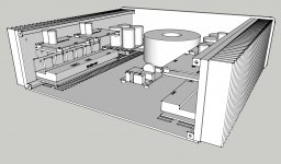
Here's my Sketchup layout with the top cover and rear panel removed:
The Intelligent Soft Start module and the Modulus-686 include some surface-mount devices and are supplied fully-built, but I bought the Power-686 and Modulus-86 as bare boards to save some money. Tom maintains project component lists at Mouser, which worked very well for ordering the large number of components I needed for this project.
Once I had received the Neurochrome products from Tom and the box of bits from Mouser, I could block out each module in Sketchup and work on my layouts and cable runs. Although the final arrangement looks quite spacious, it's really rather cramped. The main requirement is to mount all the amplifier modules on the heat sinks and to allow free air movement around them, while keeping power and signal cables well separated from each other. The latter point obviously applies to the rear panel too, and I spent a lot of time working on the layout of the input and output connectors. Once I was confident that I could actually make this work, I ordered the Dissipante chassis.
Here's a view of the interior looking towards the rear and showing the input and output connectors - it's a bit cramped, but should be workable:
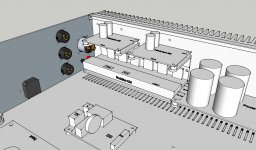
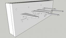
I had to stack the Modulus-86 amplifiers above the Modulus-686 to get it all into a 3U x 400 chassis. The Modulus-686 is supplied with an integral mounting bracket, but I had to come up with some way of attaching the Modulus-86 boards and of supporting the Power-686 power supplies. I went through various arrangements of stand-offs and brackets, but they were all very untidy. Eventually I decided to make some simple L-brackets, and to make them sturdy enough to be self-supporting cantilevers. The result is an interior that is remarkably uncluttered - at least until I run the cables.
Next: preparing to build.
My final arrangement comprised:
One AnTek 500VA toroidal transformer;
One Neurochrome Intelligent Soft Start module to control the transformer's in-rush current;
Two Neurochrome Power-686 power supply modules;
Four Neurochrome Modulus-86 amplifier modules;
Two Neurochrome Modulus-686 amplifier modules;
One Dissipante 3U x 400 chassis;
Various Neutrik XLR and SpeakOn connectors;
An IEC power inlet, an on/off switch, a pair of binding posts;
Miscellaneous power and signal cable, fasteners and cable ties.
Here's my Sketchup layout with the top cover and rear panel removed:

The Intelligent Soft Start module and the Modulus-686 include some surface-mount devices and are supplied fully-built, but I bought the Power-686 and Modulus-86 as bare boards to save some money. Tom maintains project component lists at Mouser, which worked very well for ordering the large number of components I needed for this project.
Once I had received the Neurochrome products from Tom and the box of bits from Mouser, I could block out each module in Sketchup and work on my layouts and cable runs. Although the final arrangement looks quite spacious, it's really rather cramped. The main requirement is to mount all the amplifier modules on the heat sinks and to allow free air movement around them, while keeping power and signal cables well separated from each other. The latter point obviously applies to the rear panel too, and I spent a lot of time working on the layout of the input and output connectors. Once I was confident that I could actually make this work, I ordered the Dissipante chassis.
Here's a view of the interior looking towards the rear and showing the input and output connectors - it's a bit cramped, but should be workable:

I had to stack the Modulus-86 amplifiers above the Modulus-686 to get it all into a 3U x 400 chassis. The Modulus-686 is supplied with an integral mounting bracket, but I had to come up with some way of attaching the Modulus-86 boards and of supporting the Power-686 power supplies. I went through various arrangements of stand-offs and brackets, but they were all very untidy. Eventually I decided to make some simple L-brackets, and to make them sturdy enough to be self-supporting cantilevers. The result is an interior that is remarkably uncluttered - at least until I run the cables.
Next: preparing to build.
Preparing to Build
Most of my projects are 80% planning and 20% execution. This allows me to refine my ideas over a long period and to have a high level of confidence in the final decision. Once I'm ready to execute, I want to get it done reasonably quickly. I'm a little impatient and can soon lose interest if a project stalls. The only thing worse than an unfinished project is an abandoned one.
With this project, it took me a couple of years to think about whether I should build a new amplifier at all, and to start an intermittent email conversation with Tom. Once I decided that I really should get on with it, I wrote to Tom one Sunday afternoon in January to begin a detailed discussion on what I should build. With his help, I reached my decision, placed an order, and received the parts on the following Sunday!
Once I had placed the order with Tom, I could download the design documentation from his Neurochrome website, which I then printed out, bound with my simple but indispensible binding machine, and read several times. Then I ordered the transformer from AnTek and the parts kits from Mouser. A couple of components were out of stock at Mouser, but I was able source them at DigiKey. There were several other items that I wanted, so I bought those from DigiKey too to boost the value of the order to qualify for free shipping.
Tom is not only a first-class designer, but he has tremendous attention to detail and a meticulous approach to everything he does. His circuit boards are works of art - it seems almost sacrilegious to contaminate them with gobs of solder. His design docs are similarly well presented, right down to revision control. This might be a good time to point out that I'm a mechanical guy and know little about electronics, which means that I'm entirely dependent on good, clear instructions. Even so, there were still a few things that I failed to grasp, but Tom always responded promptly and got me back on track.
After all the parts were on hand, I could make some basic measurements and get working on some layouts in Sketchup. I spent a lot of time over about six weeks working through this until I had a final design that I liked. At this point, I ordered the Dissipante chassis from the diyAudio Store. It shipped from Italy within 24 hours and arrived here in Canada a week later. Shipping was US$8 (!) and I paid the usual sales taxes on the total. Very painless. The package arrived unscathed, as were the contents which were individually wrapped and well protected.
I chose the 10 mm silver faceplate with the other panels in 3 mm black anodised aluminum. At first glance, the chassis appeared to be well made and should work well. I was surprised to find that each heat sink is actually two heat sinks which will be butted together, although I doubt whether this will be noticeable. My only criticism at this point is that the bag of fasteners contains many different sizes and styles in two finishes. There's an exploded diagram showing how it all fits together, but the fasteners are not identified. Shouldn't be too difficult, but it's a little irritating nonetheless.
Before getting out my soldering iron, I wanted to be sure that I could make the L-brackets for the Modulus-86 and Power-86 boards. I have a nice little woodworking shop, but not much in the way of metal-working equipment. I found some scraps of 4" and 6" square-section aluminum extrusion in a railing fabrication shop. They use this stuff for fence and gate posts, so it's quite sturdy (1/8" thick). I asked the shop to cut me some 1" wide "rings" which I took home and cut into rough 'L' brackets on my mitre saw. With a little careful thought and a simple plywood cutting jig, I was able to trim them to shape before cleaning up the edges on a belt sander. The result is not exactly precision engineering, but should function admirably.
Here's what they look like when mounted on a heat sink:
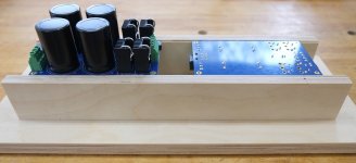
One of the things that struck me when I first looked at Tom's boards and shortly thereafter opened the box of bits from Mouser was how many components there are. Also, I was going to populate four identical amplifier boards and two identical power supply boards, so this was looking like a lot of work. I decided to build a simple support frame to hold the circuit boards the right way up for adding components and upside down for soldering. I built the frame out of two parallel plywood "walls" screwed to a plywood base. The walls each have a small rabbet along the inside top edge to trap the long sides of the boards. An extra pair of holes let me move one of the walls to accommodate both sizes of circuit board. While this wasn't a perfect solution, it did work quite well and was well worth the few minutes it took to make. Photo to follow.
Finally, I sorted all the ziploc bags of components into two piles - one for the amplifier boards and one for the power supply boards, and then labelled each bag with the part reference from the Bill of Materials in the design docs, thus I labelled the bag of 1 kOhm resistors: "R1, R6, R23", for example. This made assembly almost foolproof when it came to following the assembly instructions in the design docs. It was well worth doing.
Next: starting the build.
Most of my projects are 80% planning and 20% execution. This allows me to refine my ideas over a long period and to have a high level of confidence in the final decision. Once I'm ready to execute, I want to get it done reasonably quickly. I'm a little impatient and can soon lose interest if a project stalls. The only thing worse than an unfinished project is an abandoned one.
With this project, it took me a couple of years to think about whether I should build a new amplifier at all, and to start an intermittent email conversation with Tom. Once I decided that I really should get on with it, I wrote to Tom one Sunday afternoon in January to begin a detailed discussion on what I should build. With his help, I reached my decision, placed an order, and received the parts on the following Sunday!
Once I had placed the order with Tom, I could download the design documentation from his Neurochrome website, which I then printed out, bound with my simple but indispensible binding machine, and read several times. Then I ordered the transformer from AnTek and the parts kits from Mouser. A couple of components were out of stock at Mouser, but I was able source them at DigiKey. There were several other items that I wanted, so I bought those from DigiKey too to boost the value of the order to qualify for free shipping.
Tom is not only a first-class designer, but he has tremendous attention to detail and a meticulous approach to everything he does. His circuit boards are works of art - it seems almost sacrilegious to contaminate them with gobs of solder. His design docs are similarly well presented, right down to revision control. This might be a good time to point out that I'm a mechanical guy and know little about electronics, which means that I'm entirely dependent on good, clear instructions. Even so, there were still a few things that I failed to grasp, but Tom always responded promptly and got me back on track.
After all the parts were on hand, I could make some basic measurements and get working on some layouts in Sketchup. I spent a lot of time over about six weeks working through this until I had a final design that I liked. At this point, I ordered the Dissipante chassis from the diyAudio Store. It shipped from Italy within 24 hours and arrived here in Canada a week later. Shipping was US$8 (!) and I paid the usual sales taxes on the total. Very painless. The package arrived unscathed, as were the contents which were individually wrapped and well protected.
I chose the 10 mm silver faceplate with the other panels in 3 mm black anodised aluminum. At first glance, the chassis appeared to be well made and should work well. I was surprised to find that each heat sink is actually two heat sinks which will be butted together, although I doubt whether this will be noticeable. My only criticism at this point is that the bag of fasteners contains many different sizes and styles in two finishes. There's an exploded diagram showing how it all fits together, but the fasteners are not identified. Shouldn't be too difficult, but it's a little irritating nonetheless.
Before getting out my soldering iron, I wanted to be sure that I could make the L-brackets for the Modulus-86 and Power-86 boards. I have a nice little woodworking shop, but not much in the way of metal-working equipment. I found some scraps of 4" and 6" square-section aluminum extrusion in a railing fabrication shop. They use this stuff for fence and gate posts, so it's quite sturdy (1/8" thick). I asked the shop to cut me some 1" wide "rings" which I took home and cut into rough 'L' brackets on my mitre saw. With a little careful thought and a simple plywood cutting jig, I was able to trim them to shape before cleaning up the edges on a belt sander. The result is not exactly precision engineering, but should function admirably.
Here's what they look like when mounted on a heat sink:

One of the things that struck me when I first looked at Tom's boards and shortly thereafter opened the box of bits from Mouser was how many components there are. Also, I was going to populate four identical amplifier boards and two identical power supply boards, so this was looking like a lot of work. I decided to build a simple support frame to hold the circuit boards the right way up for adding components and upside down for soldering. I built the frame out of two parallel plywood "walls" screwed to a plywood base. The walls each have a small rabbet along the inside top edge to trap the long sides of the boards. An extra pair of holes let me move one of the walls to accommodate both sizes of circuit board. While this wasn't a perfect solution, it did work quite well and was well worth the few minutes it took to make. Photo to follow.
Finally, I sorted all the ziploc bags of components into two piles - one for the amplifier boards and one for the power supply boards, and then labelled each bag with the part reference from the Bill of Materials in the design docs, thus I labelled the bag of 1 kOhm resistors: "R1, R6, R23", for example. This made assembly almost foolproof when it came to following the assembly instructions in the design docs. It was well worth doing.
Next: starting the build.
Last edited:
Holy moly. That's quite a writeup. Your attention to detail and sense of planning is pretty clear. Thanks for sharing.
I like those angle brackets. Someone else (in the Modulus-86 build thread) made something similar from a rectangular aluminum extrusion.
I'm looking forward to pictures of the amp. 🙂
Tom
I like those angle brackets. Someone else (in the Modulus-86 build thread) made something similar from a rectangular aluminum extrusion.
I'm looking forward to pictures of the amp. 🙂
Tom
Very nice job on the planning part!
You are describing a dream amp for lots of us with active setups.
Since I use Tinkercad I haven´t looked back at, somehow making things fit into an amplifier and although Tinkercad isn´t as "precise" as other SW it helps tremendously sketching things and collecting ideas how to mount and heatsink your components.
(besides its also lots of fun and pretty quick and intuitive)
The only thing that´s missing in most CAD-SW is a model for two left hands with stubby fingers and messy cabling ;-)
Kidding aside, your enclosure looks like the perfect size!
Last edited:
Tom,
I think a bracket similar to the one you designed for the Modulus-686 would be better, but it would have to be inverted like my installation which might not suit everyone. Making such a bracket in my home shop wasn't realistic.
Joensd,
I have no idea how useful this thread might be to diy builders, so hearing that this is like a dream amp is encouraging news.
I completely agree with respect to CAD software. I use Sketchup for almost everything I make. It was particularly useful for my speakers, which have a pentagonal cross-section. Being able to readily calculate area (and thus volume) was especially useful.
I think those brackets should work well as supports.
Other than that you could mount the PCB and the LM3886 to an l-profile similar to these (LM screwed to the short side and the long side is under the PCB):
Security Check
And then finally mount that to the heatsink with two screws. Also adds more surface obviously.
These can be custom made/-cut and are cheaper than you think.
Just ordered a couple of these as I want to mount my amplifier modules vertical to save space (this will of course not be very service friendly).
That's a good idea. I hadn't thought of mounting the LM3886 to the bracket itself, even though that's exactly what Tom does with the Mod-686. I did work through several versions of a full-length bracket, but it would involve a lot more cutting which I couldn't easily do in my home shop.
Buying an extrusion for a couple of Euros is a nice solution if you can find one the size you want. I needed two widths, because I wanted to mount the power supplies the same way, hence the two sizes of gate post extrusion. Raising the power supplies allowed me to reduce the spatial conflicts between the various terminal blocks on the power supply and amplifier boards.
Using narrow brackets like mine allows more air movement around the board, although this might not be much of an issue. What it really comes down to is that I like making things!
Online Metals is a great resource for random bits of metal: OnlineMetals.com(R) | Buy Metal and Plastics at Online Metals | OnlineMetals.com(R)
I used to go to them quite a bit when I lived in Seattle. Last I checked they shipped to Canada for a somewhat reasonable price. I think they even shipped from the Vancouver area, but I could be wrong on that.
Protocase is another good outfit: Custom Electronic Enclosures for Engineers and Designers
And Send-cut-Send for flat, laser-cut metal: Online CNC cutting service for metals and plastics - Instant Quotes
Tom
Starting the Build - the Power Supplies
I decided to build the two power supply boards first; they have only a couple of dozen components and seemed quite straightforward. I made a mistake almost immediately by soldering the wrong resistor in place. Fortunately, I realised what I had done and how the mistake had come about, and was able to avoid it happening again (I think). Unfortunately, two minutes mis-soldering four resistors was followed by an hour or more of remediation. Henceforth I worked slowly and deliberately, crossing off each component in the assembly instructions as I soldered it in position.
Each power supply board holds four rectifier diodes, each with its own heat sink that clips to it. Both are soldered to the board, with thermal paste between the diode and the heat sink. First, there's no point in trying to be clean and neat with the thermal paste - it's going to get everywhere, so just get used to the idea. Second, the clips on the heat sinks are very strong and you need a minimum of three hands; I clamped the heat sink in a vice, which made life much easier. Third, soldering the heat sink to the board needs a fair amount of heat - I used a new 1/8" wide soldering bit which did the job with ease.
The final step for the power supplies was to clean them. Tom had suggested using solder with water-soluble flux,. This sounded like a good idea, although I tend to be a little sceptical of new-fangled wonder-stuff. A few seconds with a toothbrush and warm, soapy water was all it took. However, I had bought myself an ultrasonic cleaner for Christmas and couldn't resist giving it a try, so in they went for three minutes. Then I fired up my old compressor and blew most of the surplus water away. My blow gun actually whipped the top cover off one of the big capacitors, so take care if you try this - they're a bugger to get back in place. The last step was ten minutes in the oven on the plate-warming setting of 65°C (that's 150°F for those who still like to measure things in rods, poles, and perches).
The end result is a pair of quite spiffy power supplies - not quite as perfect as the ones Tom shows on the Neurochrome website and in his design docs, but certainly nothing to be ashamed of. I can't hear any water sloshing about inside those big caps, so maybe they've survived the wash and dry cycles - time will tell. Perhaps this water-soluble stuff is OK after all, although I do like the fumes of good, old-fashioned lead-based solder.
Here are the two power-686 power supplies in my assembly jig - one the right way up and the other upside down:
Next: building the Mod-86 amps.
I decided to build the two power supply boards first; they have only a couple of dozen components and seemed quite straightforward. I made a mistake almost immediately by soldering the wrong resistor in place. Fortunately, I realised what I had done and how the mistake had come about, and was able to avoid it happening again (I think). Unfortunately, two minutes mis-soldering four resistors was followed by an hour or more of remediation. Henceforth I worked slowly and deliberately, crossing off each component in the assembly instructions as I soldered it in position.
Each power supply board holds four rectifier diodes, each with its own heat sink that clips to it. Both are soldered to the board, with thermal paste between the diode and the heat sink. First, there's no point in trying to be clean and neat with the thermal paste - it's going to get everywhere, so just get used to the idea. Second, the clips on the heat sinks are very strong and you need a minimum of three hands; I clamped the heat sink in a vice, which made life much easier. Third, soldering the heat sink to the board needs a fair amount of heat - I used a new 1/8" wide soldering bit which did the job with ease.
The final step for the power supplies was to clean them. Tom had suggested using solder with water-soluble flux,. This sounded like a good idea, although I tend to be a little sceptical of new-fangled wonder-stuff. A few seconds with a toothbrush and warm, soapy water was all it took. However, I had bought myself an ultrasonic cleaner for Christmas and couldn't resist giving it a try, so in they went for three minutes. Then I fired up my old compressor and blew most of the surplus water away. My blow gun actually whipped the top cover off one of the big capacitors, so take care if you try this - they're a bugger to get back in place. The last step was ten minutes in the oven on the plate-warming setting of 65°C (that's 150°F for those who still like to measure things in rods, poles, and perches).
The end result is a pair of quite spiffy power supplies - not quite as perfect as the ones Tom shows on the Neurochrome website and in his design docs, but certainly nothing to be ashamed of. I can't hear any water sloshing about inside those big caps, so maybe they've survived the wash and dry cycles - time will tell. Perhaps this water-soluble stuff is OK after all, although I do like the fumes of good, old-fashioned lead-based solder.
Here are the two power-686 power supplies in my assembly jig - one the right way up and the other upside down:

Next: building the Mod-86 amps.
The clamps on the diode heat sinks are strong indeed. I'm actually not sure what the manufacturer's recommended mounting method is. I use a medium sized (4-5 mm), flat blade screwdriver to lift the clamp enough that I can slide the diode in. It takes a bit of work but once you've done it once or twice, the rest are pretty easy.
I usually also press the top of the heat sink with the diode mounted down on a hard surface to make sure the clamp is seated fully. Otherwise its pins won't always poke through the PCB.
Tom
I usually also press the top of the heat sink with the diode mounted down on a hard surface to make sure the clamp is seated fully. Otherwise its pins won't always poke through the PCB.
Tom
I found that I needed one hand to hold the heat sink, one hand to use the screwdriver, and one hand to insert the diode, hence the vice. For anyone just starting out, a small vice that clamps to the bench top (or table top if you're single) is an excellent long-term investment.
Building the Modulus-86 Amplifiers
The Modulus-86 amplifiers were next. They are smaller than the power supply boards and each one has around eighty components on it - and there are four of them - so it's quite a lot of work. One of the things I found that I needed most while I was soldering the power supply boards was a pair of younger eyes . . . then I remembered that I have this:
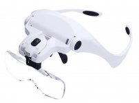
This has a selection of five lenses (I like the 2.5 magnification), LED lights, and a head strap if you need it. It works well once your brain figures it out and your eyes snap into focus.
Even with an illuminated magnifier and an assembly jig, soldering four boards took a long time. Taking a methodical approach and not rushing was the key.
Here are the four Modulus-86 boards in my assembly jig with the small stuff on them:
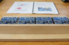
Working up through the larger components was less tedious and went faster. When all the boards were completed, I put them through the same wash / buzz / dry cycle as the power supply boards. Then I mounted all six boards on their brackets and screwed one of them to a piece of plywood in anticipation:
I'm mildly paranoid about a fastener working loose, falling off, and shorting a board, so I decided to use self-locking nuts (Nylon insert) for this application.
Next: starting on the chassis.
The Modulus-86 amplifiers were next. They are smaller than the power supply boards and each one has around eighty components on it - and there are four of them - so it's quite a lot of work. One of the things I found that I needed most while I was soldering the power supply boards was a pair of younger eyes . . . then I remembered that I have this:

This has a selection of five lenses (I like the 2.5 magnification), LED lights, and a head strap if you need it. It works well once your brain figures it out and your eyes snap into focus.
Even with an illuminated magnifier and an assembly jig, soldering four boards took a long time. Taking a methodical approach and not rushing was the key.
Here are the four Modulus-86 boards in my assembly jig with the small stuff on them:

Working up through the larger components was less tedious and went faster. When all the boards were completed, I put them through the same wash / buzz / dry cycle as the power supply boards. Then I mounted all six boards on their brackets and screwed one of them to a piece of plywood in anticipation:

I'm mildly paranoid about a fastener working loose, falling off, and shorting a board, so I decided to use self-locking nuts (Nylon insert) for this application.
Next: starting on the chassis.
magnifying glasses 5 lenses - Google Search
The white magnifying glasses all look pretty similar.
Wonder if these are enough to solder SMD down to 0805 at least.
I always shy away from buying stereo microscopes because they are so huge.
The white magnifying glasses all look pretty similar.
Wonder if these are enough to solder SMD down to 0805 at least.
I always shy away from buying stereo microscopes because they are so huge.
Illuminated magnifier
The brand I bought is "Fancii".
https://www.amazon.ca/Fancii-Headband-Illuminated-Magnifier-Visor/dp/B016N6NA92/ref=sr_1_43?dchild=1&keywords=magnifier&qid=1618778381&sr=8-43
There seems to be a number of identical products with different brand names. I chose this one because it has a lot of reviews with 87% giving four or five stars, and the vendor says that he provides a two year warranty. Also, the copy-writer wrote good English and managed to get his two apostrophes in the right places - a rare accomplishment these days.
I find that they work quite well and are good value at the price. They are a little heavy for me, but that's mainly because I have a small nose to carry the weight. However, if your bench is well lit, you won't need to use the built-in LEDs, which means you can take out the three AA batteries and considerably reduce the weight. Nonetheless, I wear them for hours at a time. A headband is included in case you need to feel more secure, but I haven't needed it.
The lenses are quite brittle - the mounting tab broke on one of them when the glasses fell off my bench, but then I shouldn't have been so careless.
Thanks. I'm familiar with Google. I've used a magnifying hood in the past, but the fresnel lens left a lot to be desired. I'd prefer a microscope, but as you say they're pretty unwieldy.
Tom
- Home
- Amplifiers
- Chip Amps
- Dual-Purpose Multichannel / Stereo Amplifier using Neurochrome Modules