So I have been working on optimising the spice sim for my design and building one out over the xmas holidays.
Finally got to the stage of plugging in and firing up the little baby. Worked first time, which is a relief, and is also whisper quiet.
Listening to her now on my workroom system. First impressions are very promising. After trimming out the DC imbalance in the OT which I can get down very low there is little sign of core staturation, which is the issue to watch for with toroidals.
Listening to some techno which doesn't seem to phase its little heart and there is plenty of power for my main system with moderate voltage gain which is what I like.
The only main issue I have is that the Back to Back power transformers are sagging quite badly and I am only getting 140VDC where I was expecting 210V. There are options to increase this though without stressing the first one any more.
If anyone is interested I will put up the final circuit diagram.
Shoog
So I have been working on optimising the spice sim for my design and building one out over the xmas holidays.
Finally got to the stage of plugging in and firing up the little baby. Worked first time, which is a relief, and is also whisper quiet.
Listening to her now on my workroom system. First impressions are very promising. After trimming out the DC imbalance in the OT which I can get down very low there is little sign of core staturation, which is the issue to watch for with toroidals.
Listening to some techno which doesn't seem to phase its little heart and there is plenty of power for my main system with moderate voltage gain which is what I like.
The only main issue I have is that the Back to Back power transformers are sagging quite badly and I am only getting 140VDC where I was expecting 210V. There are options to increase this though without stressing the first one any more.
If anyone is interested I will put up the final circuit diagram.
Shoog
LITTLE appreciated is the fact that the use of an 80 ma constant current source also serves, albeit oddly, as an anti-ripple power supply mmm… regulator? counter-regulator? buck-regulator?
There's no good word for it in common parlance. But getting constant current through your LTP-sortof-self-splitter then makes the ripply voltage on the anode-transformer rather A/C invariant.
ONE THING that really ought to help drop the distortion merit would be to give the poor tetrode screen grids a nice big pair of DC reservoir capacitors. Turn them into more of constant-voltage grids. I know … they then more-or-less simulate pentode operating conditions, but linearity will spike to your advantage. Power might also increase a bit. Or not. One never knows.
47 μF ea, might be about right. Increase the HV-to-screen resistor a bit. Get an RC constant above 100 msec. 2.2 kΩ + 47 μF gives TRC = 0.10
GoatGuy
Good info on the tail CCS. The reality is though that I have crushed the hum into submission with a four stage power supply.
At the moment I have the screen grid of the tetrode pair going staright to +B with a 720R resistor with 10 turns of magnet wire wrapped around it. I certainly could look at adding a simple RC stage to stiffen this - but only when I get the B+ boosted to its target voltage.
Whats nice to note is that this high frequency tetrode is showing no signs of instability despite minimal precautions with regard to screen and plates. the grids have suitable grid stoppers at around 4K7 though.
Really impressed with the sound of this baby - crisp and clean and punchy with diminutive 50VA OT's.
Shoog
Last edited:
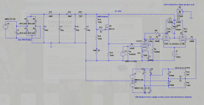
This is the final version.
Some things to note, its currently running with back to back power transformers which has worked really well for me in the past for preamp duties. However in this case the sag is significant and so i am only getting 150VDC out.
However it shows that this amp will run happily with a B+ ranging from 140-220V. The power supply is probably overkill and the amp is absolutely quite. You could probably drop one of the stages with little impact.
The QQE3-12's came from a Bulgarian seller and I got a quad for €12.00 including packaging. Since i had most of the components lying around I only had to buy a set of B9A sockets which similarly cost me just €12.00. The only thing that can be quite tricky to get hold of is the 12L8GT which usually go for about €35.00 a pair on Ebay and usually have to come from the states.
The trimmer on the 12L8GT screen is set for 70V drop across the 10K plate resistor, but this will only happen if you have the full 220V B+, still it will run happily at less.
The Trimmer on the second tetrode grid is set by setting a multimeter to the 200mV range and measuring DC between the plates of the two tetrodes (ie across the full toroidal primary winding), adjust to zero or as near as you can get.
It strains to deliver any serious power down around 20-30hz which I tested with a Leftfield track which really shakes the room, still on almost all other content there is no sign of strain.
So there you go a cheap 3 valve 5W PP amp that sounds like a SE amplifier.
Shoog
Attachments
Last edited:
Thanks, did you try other tubes for the driver? €35.00 a pair for the 12L8GT does seem a bit extravagant...
You could sub in 6AU6's which is what I modelled it for. However it wont be as Linear and you will lose that elegant 3 valve esthetic.Thanks, did you try other tubes for the driver? €35.00 a pair for the 12L8GT does seem a bit extravagant...
i had the 12L8GT's from my PP 6080 amp.
Shoog
I see, thanks for sharing the elegant design.You could sub in 6AU6's which is what I modelled it for. However it wont be as Linear and you will lose that elegant 3 valve esthetic.
i had the 12L8GT's from my PP 6080 amp.
Shoog
- Status
- Not open for further replies.
- Home
- Amplifiers
- Tubes / Valves
- Dual Pentode as two seperate Pentodes.