I have a fancy to build another self splitter PP amplifier but in an anti-triode arrangement. The driver would be used in a Schade type arrangement which would require a pentode for correct operation. I am looking at a very low powered design using QQV03-10 as the finals, but in order to make this intellectually challenging I want this to be a three valve design. So that means I need a dual pentode/tetrode as the driver.
Possible solutions are:
-choose a compactron with two separate matched pentodes. If my memory serves me correctly most of these have dissimilar pentodes in the same envelope. Another problem is that here in Europe Compactrons are rare as hens teeth and so are the sockets.
-there are quite a number of dual pentode in octal sockets which might fit the bill. i have successfully used 12l8gt's as drivers and then there are candidates like the EFF50/51. However these are all shared cathode and g2 designs. The g2 can be regulated to remove it as a confounding variable - but the shared cathode is more challenging. A possible solution might be to ground the cathode and use fixed bias on the g1's effectively cutting off the communication between pentodes.
What do people feel about option two, is it viable, or more importantly are there any real penalties to be faced. This is purely a thought experiment at this stage so all opinions are welcome.
Shoog
Even if compactrons are rare in Europe they are still dirt cheap and easily imported. Also compactron sockets are manufactured and available.
There is 6BN11 and 6J11 that are compactron twin 3.1 W pentodes. Similar tubes except for a bias V difference between them.
http://frank.pocnet.net/sheets/123/6/6BN11.pdf
http://frank.pocnet.net/sheets/201/6/6J11.pdf
6BN11 is available for $1 at ESRC:
Summer Dollar Days - Vacuum Tube Sale - $1.00 Vacuum Tubes
http://frank.pocnet.net/sheets/123/6/6BN11.pdf
http://frank.pocnet.net/sheets/201/6/6J11.pdf
6BN11 is available for $1 at ESRC:
Summer Dollar Days - Vacuum Tube Sale - $1.00 Vacuum Tubes
There is 6BN11 and 6J11 that are compactron twin 3.1 W pentodes. Similar tubes except for a bias V difference between them.
http://frank.pocnet.net/sheets/123/6/6BN11.pdf
http://frank.pocnet.net/sheets/201/6/6J11.pdf
6BN11 is available for $1 at ESRC:
Summer Dollar Days - Vacuum Tube Sale - $1.00 Vacuum Tubes
The curves look fairly dreadful in single ended applications.
Shoog
"The curves look fairly dreadful in single ended applications."
Most tubes do. That QQV03-10 has got a kink in the neg. g1 plate curves out to 125V.
The 6BN11 curves look bad simply because they didn't plot sufficiently close g1 steps, but covered a large Vg1 span. I see this on the curve tracer all the time. Purely a setup issue. Any tube can be made to look good or bad depending on grid step size.
The thing to look at is the transconductance curves on page 5. The large FLAT ramping sections indicate g1 is square law over a wide region. (Yes, most tubes are largely square law on grid1, but 1.5 law on plate or g2) Then compare these with the 300B gm curves, virtually the SAME shape. Lesson: neither are all that great for single ended, just nearly pure 2nd harmonic generators. (the 300B however gets the advantage of low Mu triode plate feedback to linearize further) (but then the 13000 gm of the 6BN11 allows super external feedback)
see page 5 for each:
http://frank.pocnet.net/sheets/084/3/300B.pdf
http://frank.pocnet.net/sheets/123/6/6BN11.pdf
Last edited:
Still not overly happy with the linearity of the 6BN11 so am thinking about using the 12L8GT (of which I have about 4) which is more linear but with much lower transconductance. Transconductance might be an issue driving those tetrode grids.
Shoog
Shoog
As you say, you can either use fixed bias or simply ensure the cathodes are well decoupled (LED bias or a big capacitor). However, self split designs normally connect the cathodes and screens together to enforce communication between them, so a dual pentode would be perfect in this regard. I am now confused about what you mean by "self splitter"?However these are all shared cathode and g2 designs. The g2 can be regulated to remove it as a confounding variable - but the shared cathode is more challenging. A possible solution might be to ground the cathode and use fixed bias on the g1's effectively cutting off the communication between pentodes.
The idea is to use a pentode as the driver (from a dual pentode valve) to drive a dual tetrode PP self splitter output stage. The driven valve will be Schaded to the driver pentode to make it behave as a triode, and the undriven tetrode will be left as a tetrode so that it slaves better to the Schaded pseudo-triode. The cathode's will be shared and provide the communication via a CCS tail. The screens will be tied together from a low impedance voltage.As you say, you can either use fixed bias or simply ensure the cathodes are well decoupled (LED bias or a big capacitor). However, self split designs normally connect the cathodes and screens together to enforce communication between them, so a dual pentode would be perfect in this regard. I am now confused about what you mean by "self splitter"?
I have designed and built such a contraption before but using EL86's. In this case each EL86 had its own CCS and was coupled to the other with a large cathode to cathode capacitor. It works well.
However I can for see an issue with a shared cathode dual tetrode in that the bias point enforced by a single CCS may create wildly different currents through the tetrode and the pseudo-triode. Then again maybe not since both are actually just running as tetrodes but one is experiencing feedback.
So the question is, does Schading a tetrode or pentode shift its g1 bias point ??
Shoog
Last edited:
I take it that you want a dual pentode driver so as to use one element for each channel. If you allow individual pentodes, much more linear ones are available for a SE driver.
Trioded curves of some driver size pentodes make it clear which are more linear at g1:
1) 6BN11/6J11 the dual unit compactrons
2) 6CB6A was used in the DCPP amp, intentional 2nd harmonic dist. for cancellation
3) 6EW6 single, similar to 6BN11
4) 6JC6 $1 list, frame grid, 3.1 Watt
5) 6LB8/6KU8/6JT8 $1 list, frame grid, 4 Watt
6) TFH $1 list, frame grid, 10 Watt
Tilt-over and 2nd harmonic progressively disappear toward the bottom of the list.
---- Schading a pentode etc should not affect the bias point if the Fdbk is AC coupled.
Attachments

Last edited:
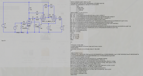
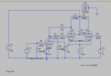
So I quickly lashed up a simulation and tested it.
It simulates really well on the driven side but until I remember how to input a transformer at the output its a bit of a guess as to the combined response.
I substituted a 6AU6 for the probable driver candidate of the 12L8GT and the output swing is roughly the same when the bias is adjusted. The self splitter output stage biases up differently as I suspected - but the outputs track each other remarkably well. Simply including an adjustable g1 negative voltage reference for the second tetrode allows for DC matching with minimal difficulty.
This looks like it could be a runner.
Shoog
Attachments
Hmmm..., V5 is positive and made last tube conduct slight more, so I think it is to compensate for the extra little current drained in Schade resistor in other side (if I analyzed correctly)?
This is an very interesting little amp! In the past some el-cheapo mini-PP amplifiers used this output splitter, of course with cathode resistor, but I never see "one-sided" PP Schade. Due to phase-spplitting output action and trafo coupling, I believe this will work fine.
This is an very interesting little amp! In the past some el-cheapo mini-PP amplifiers used this output splitter, of course with cathode resistor, but I never see "one-sided" PP Schade. Due to phase-spplitting output action and trafo coupling, I believe this will work fine.
So I remembered how to put a transformer on and did some simulations.
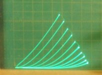
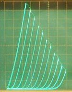
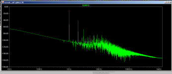
It capable of about 5W of reasonably clean output, which could be higher if the +B was pushed out to its max of 300V.
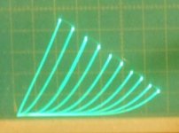
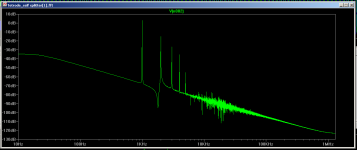
The distortion profile looks fairly typical of an SE.
The first picture is at 0.2V input and the second is at 1V input. At about 1.5V the waveform becomes flattened at the bottom and distortion rises with lots of higher components.
Overall quite a nice result.
Shoog
It capable of about 5W of reasonably clean output, which could be higher if the +B was pushed out to its max of 300V.
The distortion profile looks fairly typical of an SE.
The first picture is at 0.2V input and the second is at 1V input. At about 1.5V the waveform becomes flattened at the bottom and distortion rises with lots of higher components.
Overall quite a nice result.
Shoog
Attachments
I take it that you want a dual pentode driver so as to use one element for each channel. If you allow individual pentodes, much more linear ones are available for a SE driver.
Trioded curves of some driver size pentodes make it clear which are more linear at g1:
1) 6BN11/6J11 the dual unit compactrons
2) 6CB6A was used in the DCPP amp, intentional 2nd harmonic dist. for cancellation
3) 6EW6 single, similar to 6BN11
4) 6JC6 $1 list, frame grid, 3.1 Watt
5) 6LB8/6KU8/6JT8 $1 list, frame grid, 4 Watt
6) TFH $1 list, frame grid, 10 Watt
Tilt-over and 2nd harmonic progressively disappear toward the bottom of the list.
---- Schading a pentode etc should not affect the bias point if the Fdbk is AC coupled.
I can not find anything about pentode under num. 6 (TFH). Could you post some links, data?
"Could you post some links, data?"
http://www.diyaudio.com/forums/tubes-valves/278043-6ge5-triode-22.html#post4464136
Summer Dollar Days - Vacuum Tube Sale - $1.00 Vacuum Tubes
It is/was available on the $1 list at ESRC as just the single pentode version. (although these are probably long sold out now, except maybe as a smaller, somewhat different curve set, RCA "clone" version, more like a 5 or 7 Watt rating.) It was also available earlier at $1 as the pentode section of the 6AH9. The equiv. 9AH9 is still on the $1 list. The 6AG9, with a somewhat similar pentode, is still on the list at $1.
The TFH is still available from ESRC on their regular price list at $4, presumably non RCA "clone" types available that way.
Last edited:
This version measures about 13db better for a small hit on output amplitude.
It has the advantage of using one less component and it biases up evenly on the output without a bias adjustment (though experimentation might prove otherwise).
Thinking of working this up as a full circuit with a bias stack and using all my usual tricks of Toroidal Outputs and Back to back power transformers to create a simple and ultra cheap RH killer amp design.
I know this field has been ploughed many times before so there's nothing particularly conceptually original here, but there is real economy is using a dual tetrode which is rarely used for audio (available for €10.00 for a quad of NOS) and there is every indication that it should sound like a well implemented EL84 SE at a reduced cost.
Shoog
Attachments
Last edited:
An alternative point of view is that the only advantage of a single-ended output stage is the DC bias in the output transformer's core. In any other respect there are only additional hurdles to be overcome. Those who are concerned with small signal linearity (at a steep price) will try biasing the core; those concerned with large signal performance will take advantage of all the other good points of push-pull operation. Just one opinion, of course.
A balanced (or more properly, differential) *input* however is always very useful.
All good fortune,
Chris
A balanced (or more properly, differential) *input* however is always very useful.
All good fortune,
Chris
I have never been sold on the whole advantages of an SE core - thinking its mostly hype.
All my other designs have been differential front to back and I can attest to the supposed disadvantages of PP also been largely mythical.
Still there seems to be a market for SE designs and this design delivers the profile of an SE design but with all the advantages of PP iron.
Shoog
All my other designs have been differential front to back and I can attest to the supposed disadvantages of PP also been largely mythical.
Still there seems to be a market for SE designs and this design delivers the profile of an SE design but with all the advantages of PP iron.
Shoog
- Status
- Not open for further replies.
- Home
- Amplifiers
- Tubes / Valves
- Dual Pentode as two seperate Pentodes.