Can somebody please help me with the correct configuration of a wiring the analogue outputs of a dual mono Vout DAC?
I know for a current output DAC its a parallel connection,the Right + is connected to Left + and Right - is connected to L-.
Instinctively, the connection for a Vout DAC is a series connection? ie. R- connected to L+?
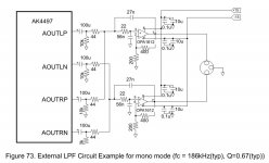
However the AKM 4497 Datasheet seems to show a parallel connection, same as a current output DAC? (see attached excerpt)
Attachments
Series connection gives you the sum of voltages. Parallel connection (via ballast resistors) gives you the average of voltages - which is half the sum, when there are two voltages. The only difference is 6dB in voltage level.
Series connection gives you the sum of voltages. Parallel connection (via ballast resistors) gives you the average of voltages - which is half the sum, when there are two voltages. The only difference is 6dB in voltage level.
Thank you. So it would appear both methods are feasible? Which of two methods gives the better SNR and/or less THD?
Judging by the ultra-low values of the Rs in that schematic, its been designed to give the highest SNR measurement possible. However the consequent loading on the DAC chip's opamps suggests SQ (dynamics in particular) is going to suffer rather badly.
Do you want to listen to this DAC or get the best possible measurements?
Do you want to listen to this DAC or get the best possible measurements?
Judging by the ultra-low values of the Rs in that schematic, its been designed to give the highest SNR measurement possible. However the consequent loading on the DAC chip's opamps suggests SQ (dynamics in particular) is going to suffer rather badly.
Do you want to listen to this DAC or get the best possible measurements?
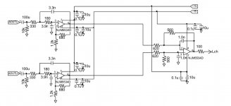
So it is actually a AK4490 Dual Mono DAC and the actual LPF circuit is as per the attachment. I am just using the principles of the AK4497 schematic. The first resistor is 660 Ohms (double what is shown to compensate for the two DAC channels connected in parallel). It sounds very good but I wonder whether I am getting the best results with this configuration and whether I might get better results with a series connection?
Instinctively the series connection should provide better SNR?
Attachments
Ok so to wire the circuit in series, would I need to soft invert the output of one of the channels?
Sent from my iPhone using Tapatalk
Sent from my iPhone using Tapatalk
So this is the Cirrus way, see page 25 of the WM8740 Datasheet. Completely different but I suspect better.
https://www.cirrus.com/cn/pubs/proDatasheet/WM8740_v4.4.pdf
Sent from my iPhone using Tapatalk
https://www.cirrus.com/cn/pubs/proDatasheet/WM8740_v4.4.pdf
Sent from my iPhone using Tapatalk
So this is the Cirrus way, see page 25 of the WM8740 Datasheet. Completely different but I suspect better.
https://www.cirrus.com/cn/pubs/proDatasheet/WM8740_v4.4.pdf
Sent from my iPhone using Tapatalk
What board are you using to play with the AK4497?
Don't believe boards for the AK4497 are available yet awaiting the chip to go into mass production in summer?
I am playing with the DiyinHK AK4490 boards.
Sent from my iPhone using Tapatalk
I am playing with the DiyinHK AK4490 boards.
Sent from my iPhone using Tapatalk
How many boards are you using/planning to use for the dual mono balanced version, four?
Last edited:
How many boards are you using/planning to use for the dual mono balanced version, four?
Currently using two configured as shown in the AK4497 datasheet but I feel like I am missing out on the possible 3dB improvement? Yes I intend to use 4 ultimately but not sure how they should be configured yet. This is what I am researching.
So it looks like you are preparng youself to remove the old chips from the boards and install the news ones. This will be a pain unless you destroy the AK4490s I guess.
I have a hot air station so removing and replacing the chip is not an issue but to be honest I have not even checked whether it's a drop in replacement.
Just trying to get the best possible out of the AK4490 at the moment.
Sent from my iPhone using Tapatalk
Just trying to get the best possible out of the AK4490 at the moment.
Sent from my iPhone using Tapatalk
I am afraid I have bad news for you (and for the rest of us). The block diagram and chip pinout are different. The AK4490 is a 48 pin and AK4497 64 pin design.
See pages 4 for Block Diagram and 5 for chip Pin Configurations.
http://www.akm.com/akm/en/file/datasheet/AK4497EQ.pdf
http://www.akm.com/akm/en/file/datasheet/AK4490EQ.pdf
See pages 4 for Block Diagram and 5 for chip Pin Configurations.
http://www.akm.com/akm/en/file/datasheet/AK4497EQ.pdf
http://www.akm.com/akm/en/file/datasheet/AK4490EQ.pdf
Last edited:
I was thinking I should try the new 140dB Sabre next so not too bothered. Having said that there has been no sign of either the AK4497 or the Sabre 9038 thus far so I suspect it is a 6 month wait as a minimum before boards appear for these?
Sent from my iPhone using Tapatalk
Sent from my iPhone using Tapatalk
So this is the Cirrus way, see page 25 of the WM8740 Datasheet. Completely different but I suspect better.
https://www.cirrus.com/cn/pubs/proDatasheet/WM8740_v4.4.pdf
Sent from my iPhone using Tapatalk
Ok so having studied this, it's no different in principle from the AKM method. This is still just running the two channels in parallel so I can't see where the 3dB improvement is coming from!?
Anybody know of any reference for a series connection which would end up doubling the voltage, not current?
Sent from my iPad using Tapatalk
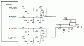
Fixed shcematic
So I have been thinking exactly along these lines? The first stage is a differential circuit with an LPF filter. The second stage is a balanced to single ended converter which is unnecessary in my case because I need a balanced output. So I think in this schematic, either the left or the right channel (but not both) needs its analogue outputs inverted and whichever channel is inverted becomes the negative pin?
Is there somebody who can verify this?
If this works, it is very minimal modification to the DiyinHK board to get the mono output from the current L and R single ended outputs.
Appreciate your input n_dori
Sent from my iPad using Tapatalk
- Status
- Not open for further replies.
- Home
- Source & Line
- Digital Line Level
- Dual Mono wiring for a Vout DAC


