I built a dual 10" box on a tight budget for a coworker, to fit up against the back seat in the trunk of a Honda Civic.

CompR10 as measured, 2 ohm DVC in series for 4 ohm
They already had a pair of kicker CompR10's, which is a high Q (.8 qts measured) driver, so I tuned it down quite a lot from kicker's recommendation to avoid a truly massive hump around 60hz. I like bass, but I'm only interested in 'lots of it' under 30 or 40 hz, and even after cabin gain I think it would have been way louder at 60-70hz than 30-40hz, which is not something I enjoy. This person had liked a previous build I made with the same frequency response shape goals in mind, so I went with my gut. (never posted it, but it was basically an LLT for a pair of GRS 10SW-4; around 2.5ft^3 each tuned to 35hz. Ginormous box, but nice deep bass for the budget, pretty smooth frequency response with no big peaks, and it uses a tiny amp that doesn't dim the lights)
I hear a transmission line is The Way To Go to tame/use high Q subwoofers, does anyone agree that would have been a better idea than just downtuning a bass reflex?
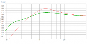
Kicker's recommended minimum size vented in red (both drivers) : 2.5ft^3 @ approx 45hz. (Port is 42 square inches by 20 inches long)
I went with (Green line): 2.5ft3@ 30hz (port is 25 square inches by ~26 inches long).
Max vent air speeds are lower above 32hz, higher below that, compared to kicker's design. Excursion is higher around 50hz, but far lower down low. Group delay is better everywhere above 28hz. I considered those acceptable tradeoffs for a better natural frequency response.
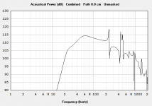
Hornresp
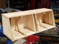
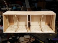
The vent joins up in the middle; it is half width on each side. I don't know if there are any downsides to this; I've seen commercial designs where they brought the ports to the middle the same way, but then left a divider board in between them. Seems like a waste of space and weight to me? The port is braced to the back in several places and across the middle at least once; those aren't in the 3D design and I didn't take a lot of pictures.
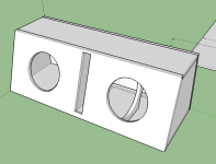
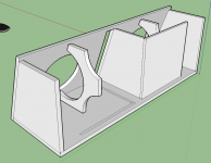
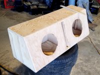
I used one fifty dollar sheet of 3/4" shop ply for the exterior (it looked better than the alternatives), and some 1/2" baltic birch I already had for the inside port walls. I delivered it rough and they finished sanding and painting it. No measurements (I think I took an impedance sweep to confirm the tuning is all) and no final photos, apologies. Reports are the user is happy with it. Fits well in the trunk, with room for excursion before hitting the seats, and very little wasted space on the sides.

CompR10 as measured, 2 ohm DVC in series for 4 ohm
They already had a pair of kicker CompR10's, which is a high Q (.8 qts measured) driver, so I tuned it down quite a lot from kicker's recommendation to avoid a truly massive hump around 60hz. I like bass, but I'm only interested in 'lots of it' under 30 or 40 hz, and even after cabin gain I think it would have been way louder at 60-70hz than 30-40hz, which is not something I enjoy. This person had liked a previous build I made with the same frequency response shape goals in mind, so I went with my gut. (never posted it, but it was basically an LLT for a pair of GRS 10SW-4; around 2.5ft^3 each tuned to 35hz. Ginormous box, but nice deep bass for the budget, pretty smooth frequency response with no big peaks, and it uses a tiny amp that doesn't dim the lights)
I hear a transmission line is The Way To Go to tame/use high Q subwoofers, does anyone agree that would have been a better idea than just downtuning a bass reflex?

Kicker's recommended minimum size vented in red (both drivers) : 2.5ft^3 @ approx 45hz. (Port is 42 square inches by 20 inches long)
I went with (Green line): 2.5ft3@ 30hz (port is 25 square inches by ~26 inches long).
Max vent air speeds are lower above 32hz, higher below that, compared to kicker's design. Excursion is higher around 50hz, but far lower down low. Group delay is better everywhere above 28hz. I considered those acceptable tradeoffs for a better natural frequency response.

Hornresp
The vent joins up in the middle; it is half width on each side. I don't know if there are any downsides to this; I've seen commercial designs where they brought the ports to the middle the same way, but then left a divider board in between them. Seems like a waste of space and weight to me? The port is braced to the back in several places and across the middle at least once; those aren't in the 3D design and I didn't take a lot of pictures.


I used one fifty dollar sheet of 3/4" shop ply for the exterior (it looked better than the alternatives), and some 1/2" baltic birch I already had for the inside port walls. I delivered it rough and they finished sanding and painting it. No measurements (I think I took an impedance sweep to confirm the tuning is all) and no final photos, apologies. Reports are the user is happy with it. Fits well in the trunk, with room for excursion before hitting the seats, and very little wasted space on the sides.


Did you break in those drivers before measuring them? The Fs looks noticeably higher than the published one - see https://www.kicker.com/app/tsparam/48CWR102.html.
Note that the actual response at higher bass frequencies might differ a bit from the Hornresp sim due to the high inductance of the driver and the likelihood that the motor does not contain any shorting rings or similar to minimize variations in inductance at different frequencies.
The box design looks like exactly what would I have gone with (maybe I'd have gone with a slightly smaller box, but I'd still go for the low tuning, which basically defines how low the subwoofer is going to go without significant distortion). my mantra for ported car audio boxes is tune for low frequency limit, size box for best in-band power-handling, then fix the response with EQ. Normally I just go with sealed builds (and fix the response with EQ 🙂 ).
As for TLs, most of the "car audio" ones are just "bass whistles", designed to resonate at a low frequency without regard to what the entire passband is going to look at. They can be fun, but probably not accurate, especially if you use a high-Q low efficiency subwoofer for the build. Done right for bass duty though and you can minimize any sort of port compression effects at low frequencies. See http://www.diysubwoofers.org/tls/
Did you break in those drivers before measuring them? The Fs looks noticeably higher than the published one - see https://www.kicker.com/app/tsparam/48CWR102.html.
Hi @Brian Steele
Just got a response on that: yes, surprisingly, they were well-used before they went into this project.
Would this be shown by turning on Lossy Inductance? Should I? I thought I've heard it's only for 'high inductance' drivers, but I've never heard a guideline on how to decide how much is 'high'. Presumeably it would be a ratio of inductance over RE, being greater than some threshold?Note that the actual response at higher bass frequencies might differ a bit from the Hornresp sim due to the high inductance of the driver and the likelihood that the motor does not contain any shorting rings or similar to minimize variations in inductance at different frequencies.
And/or, would it be shown by using the Semi-inductance model (if I came up with the calculated values)?
Thank you for the info! I'm a big fan of your site.