I built a preamp fashioned after a Fender design. Instead of using the Hi-LO dual jacks, I used only one input jack.
I would like to add a second input jack on the back of the chassis. Both should work independently - i.e. one or both jacks open or closed with inputs won't affect the other in any way.
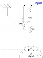
Currently, my single input goes through a 68K resistor before grid 1. When open, there is a 1M resistor before the 68K, wired to ground.
When the jack is closed, the signal grounds directly to the chassis.
I have a 33K resistor on a switch to toggle an additional padding effect like the original Hi - LO input circuit. I'd like this switch to be able to pad my new rear input as well
Can I simply duplicate the front jack - 68K to G1 with a 1M resistor to ground? It looks like there will still be a short to ground through the other jack this way.
Can I just connect the second input jack to the same points the first is connected to? I seem to remember trying this once and it didn't work. - Both switches had to be open to keep the signal away from ground or none would work, etc.
I have never been able to really get my head around the simple, but confusing, HI-LO dual-jack scheme. Ideas?
I would like to add a second input jack on the back of the chassis. Both should work independently - i.e. one or both jacks open or closed with inputs won't affect the other in any way.
Currently, my single input goes through a 68K resistor before grid 1. When open, there is a 1M resistor before the 68K, wired to ground.
When the jack is closed, the signal grounds directly to the chassis.
I have a 33K resistor on a switch to toggle an additional padding effect like the original Hi - LO input circuit. I'd like this switch to be able to pad my new rear input as well
Can I simply duplicate the front jack - 68K to G1 with a 1M resistor to ground? It looks like there will still be a short to ground through the other jack this way.
Can I just connect the second input jack to the same points the first is connected to? I seem to remember trying this once and it didn't work. - Both switches had to be open to keep the signal away from ground or none would work, etc.
I have never been able to really get my head around the simple, but confusing, HI-LO dual-jack scheme. Ideas?
The hi/lo thing is easy enough, but first your jacks. Why not parallel the front and rear jacks? Instead of grounding each tip in the jack, Run ground up to one cutout, then series that to the other jack cutout, so either jack, when used opens the ground shunt.
Hi/lo: In the high jack, the two 68k resistors are put in parallel by the cutout contact in the low jack. That leaves a 34k resistance in series with the grid. In the low jack, the high jack still has its 68k grounded, while the low jack 68k is not. That results in the two resistors being in series across the low jack and ground, with the signal to the grid coming from their junction. Those two resistors thus form a voltage divider, cutting teh signal voltage in half going into the grid. That is a 6db reduction.
Hi/lo: In the high jack, the two 68k resistors are put in parallel by the cutout contact in the low jack. That leaves a 34k resistance in series with the grid. In the low jack, the high jack still has its 68k grounded, while the low jack 68k is not. That results in the two resistors being in series across the low jack and ground, with the signal to the grid coming from their junction. Those two resistors thus form a voltage divider, cutting teh signal voltage in half going into the grid. That is a 6db reduction.
Hi Enzo, thanks for taking the time.
Well, if one jack is used and the other isn't, won't that still shunt the signal to ground? i.e. - the unused jack still closes the overall ground shunt.
I'm pretty sure I did this once - and the only way to make it work was to have a dummy jack inserted in any unused input if both weren't being used.
I get how the HI-LO jack works in theory. It's that the way it's wired is one of those "so simple it's genius" things which baffles me to no end, LOL
Can you draw a picture? My schematic brain works on visual schematics, not imaginary ones in my head.
Better than a picture, here's the schematic of what I have now. EDIT : Well, it's the layout map, but you get the idea.Can you draw a picture? My schematic brain works on visual schematics, not imaginary ones in my head.
Attachments
Last edited:
Enzo is right.
If you plug into the one where the cutout is grounded it opens it and you are good to go.
If you plug into the other jack it disconnected the tip from the cutout connection, which goes to the other cutout connection which is grounded, but you just cut it out so no problem.
Your second jack will look exactly like this, a 68K, a 1M, except, the cutout lug will not go to ground, but to the cutout lug on the first jack.
The unused jack won't have it's tip grounded, but it doesn't matter I guess because you are driving it with the input signal. It does leave it floating with 68K to keep the noise out, but that is probably low enough. Maybe it would be better to just have a single 68K resistor?
You're a clever guy Enzo!
Last edited:
If the unused jack still has it's tip grounded via the cutout, and both tips are now connected to the G1 input - won't that also ground the one in use?
IOW, it doesn't matter where the second jack's cutout lug is connected, the signal is still grounded if one jack isn't in use (?)
Clear as mud?
IOW, it doesn't matter where the second jack's cutout lug is connected, the signal is still grounded if one jack isn't in use (?)
Clear as mud?
I suggested putting the cutouts in SERIES. Both jacks wired in series. Plugging into either one breaks the ground shunt.
Wire the tip cutout of one jack to the tip itself of the other, then wire THAT cutout to ground. Now with both open jacks both tips are grounded, and plugging into one or the other opens that series string to ground.
Wire the tip cutout of one jack to the tip itself of the other, then wire THAT cutout to ground. Now with both open jacks both tips are grounded, and plugging into one or the other opens that series string to ground.
Here, look at the input jack wiring here, one jack is up front and the other in back.
http://bmamps.com/Schematics/Peavey/Peavey_Valverb_Schematic.pdf
http://bmamps.com/Schematics/Peavey/Peavey_Valverb_Schematic.pdf
Ok - I see it. Thanks for the schem, that helps a lot!
Trying to visualize the tip contact wired to the cutout contact on the other jack might have been what was throwing me.
THANK YOU!
Trying to visualize the tip contact wired to the cutout contact on the other jack might have been what was throwing me.
THANK YOU!
Just for my sake, now that you see it, does my original word description seem more clear? Or not?
Nothing more clever on my part than remembering an example in commercial gear. I THINK the old ADA MP1/2/3 preamps had that as well, but I might remember wrong..
Nothing more clever on my part than remembering an example in commercial gear. I THINK the old ADA MP1/2/3 preamps had that as well, but I might remember wrong..
Well, it's as I originally suspected.
Use of the front (J101 in the schem) disables the back (J103).
I found the original Peavey Valverb manual, and it confirms that use of its front jack disables the rear one.
I'll go with this for now, because I think any time I'd plug into the front, I wouldn't want the back in use anyway. BUT I'd still love to have each work independently.
- Now it's a puzzle 🙂
I was thinking about this, and what if you just didn't terminate it? No short when it's unplugged. You'd still have the 1 Meg to ground, so it's not totally floating. As soon as you plug something in it doesn't matter. Then you could have one or both plugged in.
The two guitars are going to load each other down. But so what? It's kind of a weird thing to do anyway.
My son had a small Fannon FMA-20 PA tube amp with dual 7189's and some 12ax7's at the input. it had 2 mic inputs that he was using as the guitar inputs. But each one went to it's own 12ax7 tube input. That's the right way to do this.
You can isolate the signals with resistors, but you will reduce the signal levels.
Perhaps a low noise opamp cicuit with two inputs and two opamps to isolate the signals and mix them after they come out of the opamp.
I wouldn't want to use both inputs at once anyway, they will be force mixing the signals in the jacks.
If you want to be able to use either one all th time, just mount a simple A/B switch.
The basic wiring I suggested allows you to plug into either jack at will, but not both. The only time you would use both is to have two competing inputs plugged in, not desirable.
You could still wire up both to work with muting, but you'd need to use jacks with extra contacts, like TRS jacks. Similar to the Peavey example, you'd wire the #1 jack cutout contact to the tip, then the #1 ring to the #2 cutout, and then #2 ring to ground. That leaves both tip contacts unused in the muting, so you can wire both with series resistors to the input circuit.
This is mostly my thinking now as well - Why would I use two inputs simultaneously anyway? All I was worried about was being able to use the front jack in an emergency (like outboard power supply goes down, and need to quickly plug in another instrument). The front jack grounds and overrides the rear jack now if it's in use (I think), so I don't think there would be signal loss if I use the front input occasionally.I wouldn't want to use both inputs at once anyway, they will be force mixing the signals in the jacks.
- Status
- Not open for further replies.
- Home
- Live Sound
- Instruments and Amps
- Dual Jack Inputs without the HI-LO effect? Fender / Marshall