How can I simulate a dual 8" driver horn in hornresp?
To specify multiple drivers, choose Driver Arrangement from the Tools menu, or simply double-click on the disabled Nd text box, in Edit mode.
yeah but it I want to make a dual 8" tapped horn and I want one in back of the other! so the box can be "slim" but the s1 of the first driver and the s1 of the second driver is not the same! hornresp calculate this or?
S1 or L1?
L1 would be the average to the two drivers.
S1 would be the area that the drivers face into.
The double Sd is taken in account by the software when you tell it that there are two drivers.
L1 would be the average to the two drivers.
S1 would be the area that the drivers face into.
The double Sd is taken in account by the software when you tell it that there are two drivers.
I'm not a expert but I this S1 is the therm a mean!
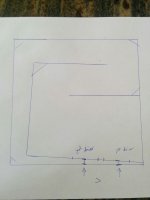
I made a hand drawing because I don't have de time right now to make a more precise drawing!
you can see that the space between the cone of the 1st driver and the bottom of the horn isn't the same as the space between the second driver and the bottom of the box!
am i wrong?
I made a hand drawing because I don't have de time right now to make a more precise drawing!
you can see that the space between the cone of the 1st driver and the bottom of the horn isn't the same as the space between the second driver and the bottom of the box!
am i wrong?
Attachments
You do mean S (area in front of the cone is S2)
S1 is the area at the end of the horn.
ahh ok thanks but how can I simulate a horn with two different S2?
ahh ok thanks but how can I simulate a horn with two different S2?
For the purposes of the simulation, the two drivers are treated as a single composite driver. Set S2 equal to the cross-sectional area of the horn midway between your two actual drivers (in other words, half way between the two arrowed lines shown in your sketch).
For the purposes of the simulation, the two drivers are treated as a single composite driver. Set S2 equal to the cross-sectional area of the horn midway between your two actual drivers (in other words, half way between the two arrowed lines shown in your sketch).
ohhh thanks! but the simulation will not be verry accurate? and what about the S1? the S1 of the first driver should be different form the 2nd driver? I don't know the parameters of HR very well :$ but ai think S1 is the space at the beginning of horn?
S1 is the area of the end of the horn.
You already confirmed that you had read and understood that with
You already confirmed that you had read and understood that with
ahh ok thanks
yeah but when I look at these pictures I see that S1 is the begenning of the horn but maybe that's what you mean! what I mean is L12, sorry! the L12 of the 1st and the 2nd driver will be different? and the L23 too!
I took half way? between the first and the second driver?
from the S1 to the S2 and the S2 to the S3 but the S3 will be between the two driver too?
I took half way? between the first and the second driver?
from the S1 to the S2 and the S2 to the S3 but the S3 will be between the two driver too?
Attachments

ohhh thanks! but the simulation will not be verry accurate? and what about the S1? the S1 of the first driver should be different form the 2nd driver? I don't know the parameters of HR very well :$ but ai think S1 is the space at the beginning of horn?
The predicted results will be reasonably accurate for the frequency range you are interested in. For the purposes of setting up your simulation model, simply think of the two drivers as a single driver, but with twice the area (the Hornresp composite model automatically changes the other driver parameters as necessary, when calculating results).
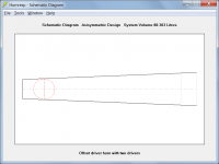
Attachment 1 shows an offset driver horn with a single driver. Attachment 2 shows the offset driver horn but with two of the same drivers specified. Notice how the driver area has doubled because it is now a composite driver. The centre of the composite driver is positioned where the cross-sectional area of the horn is S2, and is located at distance L12 from the beginning of the horn.
Attachments

Nice! very nice! I'm looking to build a 2x12" (lab12) tapped horn for a friend! his father is quite nice, he give us the right to put this right in the cinema room 🙂 your help is realy... helpful 🙂
I'll uptade if I had other questions that i can't find answers on the internet! 🙂
thanks 🙂
I'll uptade if I had other questions that i can't find answers on the internet! 🙂
thanks 🙂
- Status
- Not open for further replies.
- Home
- Design & Build
- Software Tools
- dual driver in hornresp?