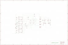
This is a design for a dual bank floating supercap power supply. TL431 are used as voltage sensors, 2 for each bank, along with logic to keep the A and B supercap banks between a max and min voltage. The bank connected to the output is isolated from the supply charger by the relay, and thus will have leakage current determined by the relay -- zero for electromechanical and generally less than one uA for SSR.
The supercaps are placed in series. This circuit employs the ALD8100XX supercap balancing quad mosfet chip, so one chip for each 10v or so of supply assuming 2.7v supercaps. The modules can be placed in series to generate 10,20,30V supplies as needed.
The output will vary between the min and max voltages, a follow-on regulator can make a precise supply voltage.
The output voltage is truly floating.
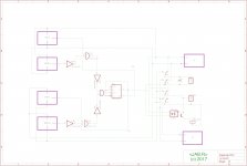
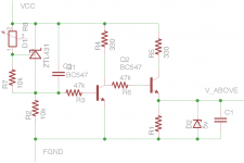
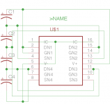


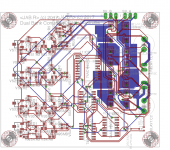
This board uses the NXP PSMN075-100MSE MOSFET to implement the relays -- datasheet indicates 10nA leakage current typical. I've used the TL431 and an NPN to make the +5V logic supply. On the left are the 4 TL431 based voltage sensors. Lower middle are the 4 logic chips. Above these to the right are the MOSFETs, and above to the left the series regulator.

Are you using the design?
Are you going to sell pcbs or make gerbers available?
Thanks
I'm not using it yet but plan to. Still working out some details of the supercap board vs battery boards (what is posted will work with these other modules). If there is enough interest we can make a run of PCBs once its tested.
jborden,
Did you see the supplies being used in this thread:
https://www.head-fi.org/f/threads/r2r-da-m1-ultracap-powered-build.839007/page-6
Sounds like a great application for your boards.
Anymore progress?
Very interested!
Greg in Mississippi
Did you see the supplies being used in this thread:
https://www.head-fi.org/f/threads/r2r-da-m1-ultracap-powered-build.839007/page-6
Sounds like a great application for your boards.
Anymore progress?
Very interested!
Greg in Mississippi
Jonathan,
Got some of these boards working yet?
I really want to try this setup:
R2R DA M1 Ultracap powered build | Page 8 | Head-Fi.org
AND don't want to use timers.
DIY'ers of the world are waiting on you!
Greg in Mississippi
Got some of these boards working yet?
I really want to try this setup:
R2R DA M1 Ultracap powered build | Page 8 | Head-Fi.org
AND don't want to use timers.
DIY'ers of the world are waiting on you!
Greg in Mississippi
Jonathan,
Got some of these boards working yet?
I really want to try this setup:
R2R DA M1 Ultracap powered build | Page 8 | Head-Fi.org
AND don't want to use timers.
DIY'ers of the world are waiting on you!
Greg in Mississippi
Hi Greg, I'm incorporating these designs into projects I am working on. Each project has specific requirements that involve some degree of customization. You are free to take the schematic and have boards made for DIY purposes, or customize to your own requirements, but I'm not able to "productize" this at the moment.
The intention is to present a general approach that can be customized for specific needs.
Last edited:
- Status
- This old topic is closed. If you want to reopen this topic, contact a moderator using the "Report Post" button.
- Home
- Amplifiers
- Power Supplies
- Dual Bank Floating Supercap Supply
