Easy with REW to measure your system residual distortion, FR, etc. Simple electric design that feeds your DAC (a little jig about the same as measuring impedance), just like your mic amp feeds it. But unlikely amp contributes enough to worry about unless tubes before 1970. Nor to fuss about absolute loudness - just test loudish.
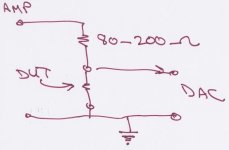
Here's a test jig. Needs a few alligator clips or you can be clever with rubber bands. "DUT", device under test, can be a resistor so you can see the FR and distortion of the whole chain ending with the amp or a speaker so you can see the relative impedance plot (really interesting to see how a BR is working or how your 32 Hz drivers are behaving).
Trick is to find "resistors" around the house to use. Most resistors in the range of interest are those that get hot like incandescent bulbs or bread toasters. Anybody with ideas?
B.
Trick is to find "resistors" around the house to use. Most resistors in the range of interest are those that get hot like incandescent bulbs or bread toasters. Anybody with ideas?
B.
Attachments
Hi Ben, interesting tips on how to find out audio chain residual noise and FR, I will read more about this topic indeed as I'm about to build the REW recommended impedance jig as well, since the Alesis audio interface can put out 0.5 W into 47 Ω headphones, so should be enough to get basic average measurement.
Guess I have to be very careful wen testing with the amplifier in the chain to avoid taking one input on the interface, since never done that previously but will find out soon.
P.S. I also forgot to add that the microphone XLR input on my interface where slightly clipping wen I was taking the measurements even at low power, so this may be another source for the distortion disparity, but subjectively comparing this subwoofers with the UM18-22 at the same xover point and output, this subs are amazingly clean wen playing heavy bass tracks such EDM, plus the chest slam midbass when crossed higher which lacked on the UM18-22.
Regards
Actually, I post RTAs (real-time spectrum plots) of music pieces now and then. Folks sometimes think there's low bass when, in truth, it is loud bass guitar at 75 Hz and not much south of that.
DIY RTA on a music piece that is playing using REW is trivially simple to do... once you have an output to analyze. Finding an output and using a Y connector into the input feed of a full-range amp may be very easy for some. Not as easy for others who are mostly digital. I can use a spare channel in my Behringer DSP as a source to feed back into REW as the music plays.
DIY RTA on a music piece that is playing using REW is trivially simple to do... once you have an output to analyze. Finding an output and using a Y connector into the input feed of a full-range amp may be very easy for some. Not as easy for others who are mostly digital. I can use a spare channel in my Behringer DSP as a source to feed back into REW as the music plays.
Hi, I agree with that, as an old bass-head wen I was a teenager that is exactly what I observed, lots of folks with car systems with just pretty loud 45~65Hz think they had very deep bass, however I know wen I had low bass playing as I actually can't hear much below 20Hz but wen I crank-up a bass tunes things just start to shake a lot.
Also sometimes I use handy utilities to check if a track(audio file) does have low bass below say 24Hz with Audacity plot spectrum, and Spek to check the acoustic spectrum.
P.S. In the mean time I found some old parts in my stuff bin to build an Impedance jig for REW and play with, I have resistors between 100,75 and 47 ohms
so still thinking what will be a good value to start with.
Start with 175 Ohms because you want a largish multiple of the DUT resistance. Just a matter of getting enough signal off the DUT to drive the REW input. But with small-sized resistors, take care not to pump to much amp power into them since a 5 watt sine wave will destroy a 1-watt 200 Ohm resistor in a few seconds, eh. Just enough to keep out of the residual mud. Start low.
An amp outputting 5 watts will have an output voltage around 7 VAC.
Should be fun for you to eyeball the impedance curve of your intact BR box (and naked driver, if you have any). Please post.
An amp outputting 5 watts will have an output voltage around 7 VAC.
Should be fun for you to eyeball the impedance curve of your intact BR box (and naked driver, if you have any). Please post.
Hi Ben, thanks for the recommend on the 175-ohms resistor, however I will start with the headphone output of the Alesis USB console first with a lower value resistor to familiarize with, I don't dare to try use the Samson S2000 amplifier initially. 😉
If the Alesis headphone output is not enough(0.5 watt @ 47 ohms regarding the specs), I could use my Lepy LP-2020A instead and re-try, lets see.
Regards
If the Alesis headphone output is not enough(0.5 watt @ 47 ohms regarding the specs), I could use my Lepy LP-2020A instead and re-try, lets see.
Regards
Should work OK and headphone amp likes playing into that kind of impedance. Might have to crank up the headphone output. No risks, I can think of. But if others have cautions, time to speak up.
First run a plain resistor as the DUT to see if you are in the ballpark for measuring OK. If you have like 10 Ohms, that will serve nicely as a reference.
First run a plain resistor as the DUT to see if you are in the ballpark for measuring OK. If you have like 10 Ohms, that will serve nicely as a reference.
Last edited:
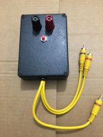
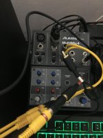
Hi Ben, sorry a bit late on t his JIG build/setup, I got some time and built the impedance measurement Jig and connected it to my old USB audio interface, an Alesis MultiMix4 USB(with monitor on/off modification) and ran a quick test.Should work OK and headphone amp likes playing into that kind of impedance. Might have to crank up the headphone output. No risks, I can think of. But if others have cautions, time to speak up.
First run a plain resistor as the DUT to see if you are in the ballpark for measuring OK. If you have like 10 Ohms, that will serve nicely as a reference.
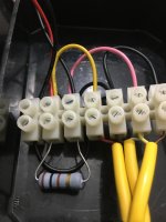
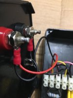
Since this is my first experience with REW + Impedance/Jig, I will post the build images for reference and the first dummy test results so I can have some advice if they does not look appealing for subwoofer measurements.
Interface calibration, red button press momentary shorts sense resistor:

Measurement with a 10-ohm resistor(measured about 9.9-ohm on my DMM):

I've noticed that the impedance start dropping between 5~6Hz, and getting abit noisy over 4Khz, however since this is for home measuring subwoofers to get an approximation of the box tuning mainly, it seems that the recommended 100-omh sense resistor is ok with this audio interface, though I can easily swap the sense resistor if needed.
Regards
Attachments

The good ol' "built like a brick outhouse". Fancy. Nice. Gosh, I wonder how flat the system is below 2 Hz? Actually, suspiciously flat and extended... but just changing the benchmark resistance should confirm it is measuring the resistor and not something false.
When you get to check the speaker, use the REW "Overlay" button to plot the benchmark and the speaker on the same picture.
But for others reading this thread, with these low impedances, just loose alligator clips with no shielding would be fine.
When you get to check the speaker, use the REW "Overlay" button to plot the benchmark and the speaker on the same picture.
But for others reading this thread, with these low impedances, just loose alligator clips with no shielding would be fine.
I've took few measurements and they look similar, so looks like there is no variations in the audio interface and jig counterparts, however as I've though the tune looks a little lower that the WinISD prediction, so I will post both graphs for comparison.
WinISD impedance prediction:

REW/Jig box measurement in pleace:

Between I've read somewhere that WinISD over calculates the port length by between 10~15%, plus the subwoofer box is placed in the corner very tight close to walls effectively extending the port length thus dropping the tune slightly, also there are 2x big pillows per box too, so seems the tune is between 17~18Hz regarding REW+Jig. 🤔
WinISD impedance prediction:
REW/Jig box measurement in pleace:
Between I've read somewhere that WinISD over calculates the port length by between 10~15%, plus the subwoofer box is placed in the corner very tight close to walls effectively extending the port length thus dropping the tune slightly, also there are 2x big pillows per box too, so seems the tune is between 17~18Hz regarding REW+Jig. 🤔
I've used an 47-ohm as a DUT just to be sure the Jig setup is reading properly, looks like is close enough.

Nice stuff. BR. Clear X-ray of cone motion.
You can also see the value of bracketing the speaker plot with plots of a highish and lowish resistor on the same picture.
Seems you have a lot of cone motion just south of 50 Hz and that is also where the box/port adds to the output (but at the lower motion bump, the port subtracts from the speaker's output being contrary phase). Prolly sounds great because (if truth be known) hardly anything below 40 Hz worth fussing about on normal recordings and that low-end boost is helpful.
Although impedance is complex, looks like you don't need to sweat about Zobel circuits and lose sleep about XOs until above maybe 400 Hz. (or ever sweat anything about impedance if using active XO, like ought to be).
Last edited:
Thanks Ben for taking a look on those measurements, I will read more on this stuff indeed.
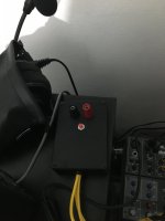
Since REW/Jig works great, I will make a decent Jig box with few sense resistance selection(maybe a rotary switch) and add speak-on connector too, also RCA and 1/4" i/o with clamping zener diodes for protection as per REW recommends.
So I have now another project to have fun with.
Regards
Since REW/Jig works great, I will make a decent Jig box with few sense resistance selection(maybe a rotary switch) and add speak-on connector too, also RCA and 1/4" i/o with clamping zener diodes for protection as per REW recommends.
So I have now another project to have fun with.
Regards
The distortion looks awful if the level is calibrated, but not likely from the amplifier at the frequencies you posted, more likely something in the room rattling. A harmonic level of 10dB below the fundamental would be around 31%HD, with the BC21SW152-4 you shouldn't see more than 10% distortion until excursion is past Xmax.I'm not sure about the distortions may look average or awful. but I agree about EQ/PEQ may add unwanted results, plus my used old-school amplifier a Samson S2000 from the yeah 1999~2000, that I haven't re-caped the electrolytic's yet may be another source of distortion as well?
The S2000 should have about 63volt maximum output before clipping, it should take around 75volts before the BC21SW152-4 would even reach Xmax (15mm) above 16Hz.
Although the amp and driver are not likely the problem, worth trying to find what is, a slow sine sweep around the suspect frequencies should help locate the source.
Nice build!
@weltersys Thanks for the clarifications in regards the distortion being related to something else rather than the amplifier/driver or the audio chain, I can confirm that I've take the measurements at low power as the room plastic windows screens and the doors where rattling a lot at the lower frequencies, also I've noticed a huge improvements in audio quality from this subs compared to my sealed 5FT^3 UM18-22 which sounded too stressed/distorted when pushed a bit.
As for the S2000 amplifier delivering the ~63v, I still haven't clipped them yet even at the non-rated 4-ohm bridged in my room, also some time ago I've opened them for cleanup and take a rail voltage measurement of one channel and I think they have enough voltage after load sag(133v/133v):

Regards
As for the S2000 amplifier delivering the ~63v, I still haven't clipped them yet even at the non-rated 4-ohm bridged in my room, also some time ago I've opened them for cleanup and take a rail voltage measurement of one channel and I think they have enough voltage after load sag(133v/133v):
Regards
- Home
- Loudspeakers
- Subwoofers
- Dual 21" Down-firing-Port Subwoofer Build