I have a 20 y/old (but nice) power amplifier, which has developed a fault in the right channel.
I am not an electronics hobbyist (yet...).
A friend (who is) re-cap'd it a couple of years ago, but logistics mean I can't get the amp to him this time. So I'm on my own.
I think I can track the fault by elimination - the circuit is a very symmetric A/B design, so I can compare the waveforms on the negative/positive sides of the circuit.
Even better, the amp is dual mono in construction. It literally has two identical boards, and the left on is working perfectly. As long as I drive a symmetrical stereo test signal in, I have an ideal source of reference voltages and signals.
My plan is to compare the left board with the right board until I find a difference, and then check components.
To this end I think I need an oscilloscope. But I don't appear to need a very fancy one. I only need audio frequencies (50 Mhz would be of surpassing irrelevance), and absolute accuracy doesn't matter much either.
I could buy a s/h "real" scope but they're pretty big and, still fetch actual money (especially shipping!!).
This thing
JYE Tech: DIY Oscilloscopes, DIY Kits for Hobbyists
appears to be the cheapest cased scope that does the sort of thing I need. The online reviews seem quite favourable (although they all point out it's not a real 'scope, which raises the question of what's "real").
The only fly in the ointment seems to be that my amplifier (at 100 W/ch) has 59v power rails, and the DSO150 has an input max of 50v.
Could I use a 10:1 resistor divider to bring me in range? And if so what value should the divider be? I'm afraid the whole input/output impedance thing is a close book to me.
I would be grateful for any help or advice.
BugBear
I would not bother with the diy scope... Do you have a soundcard in your PC/laptop? If so, just use one of the free scope software, which is sufficient for troubleshooting purpose. And yes, you need to pad down the output of the amp, or you can damage the input of the soundcard.
For analog audio, anything at about 10 MHz and above is fine. However, if you're buying a 'scope, the ones that are new enough to be reasonably reliable are probably at least 20 MHz up to perhaps 100 MHz.
Most people these days go with the soundcard / audio in and a laptop / desktop, although I do like an actual 'scope myself.
For the kind of work you are planning, a curve tracer is extremely handy.
Most people these days go with the soundcard / audio in and a laptop / desktop, although I do like an actual 'scope myself.
For the kind of work you are planning, a curve tracer is extremely handy.
My laptop has a soundcard (I assume), but I would rather risk 59v into a £20 scope than my £500 laptop!
(and some of the adapter/safety circuits for Xscope cost more than the DSO150...!!)
BugBear
(and some of the adapter/safety circuits for Xscope cost more than the DSO150...!!)
BugBear
You may well find just checking DC voltages with a meter is enough to localise the fault.
While a scope is undoubtedly the single most useful piece of test gear around, it will only confirm what you can hear such as distortion or no or low output.
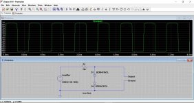
A resistor and couple of Zener diodes will protect your PC from excess voltage as shown here. The voltage is limited to the value of the zeners chosen, 6.2 volts here. The amplifier is producing a 100 volt peak sinewave. The signal is unaffected at voltages below the Zener value.
I don't think you mentioned what the amp is and what the fault is...
While a scope is undoubtedly the single most useful piece of test gear around, it will only confirm what you can hear such as distortion or no or low output.
A resistor and couple of Zener diodes will protect your PC from excess voltage as shown here. The voltage is limited to the value of the zeners chosen, 6.2 volts here. The amplifier is producing a 100 volt peak sinewave. The signal is unaffected at voltages below the Zener value.
I don't think you mentioned what the amp is and what the fault is...
Attachments
Some things just work out; the scope doesn't come with "proper" probes, just a couple of croc clips.
Further looking/shopping/checking reveals the existence of 10x probes (in some cases switchable) that will not only fulfil my need for probes, but also put the peak voltage of the measurements up to 500v.
BugBear
Further looking/shopping/checking reveals the existence of 10x probes (in some cases switchable) that will not only fulfil my need for probes, but also put the peak voltage of the measurements up to 500v.
BugBear
Just be aware that most divider probes rely totally on you connecting them to an input of 1meg ohm impedance (+ 30pF or so parallel capacitance) which is the typical scope input impedance and so they will not work correctly when coupled to anything different.
Have a look at figure 5 here which shows a typical divider probe and the correcponding scope input.
http://www.syscompdesign.com/assets/images/AppNotes/probes.pdf
http://www.syscompdesign.com/assets/images/AppNotes/probes.pdf
I'd take Mooly's advice and check the DC points, if your amp is transistorized then most anything that goes wrong will show up in a major way in the DC node values. There are a few things that won't but most will. Modern amps tend to be direct coupled, stages operating points being set by previous stages and following stages as well. You won't likely be able to trace a signal through to find when it stop as you might in a tube amp. So look at the DC values and think what might be going on -- look for operating contradictions like reverse biased junctions or forward bias voltages that are more than about 1 volt on transistors, large voltages across low valued resistors, missing supply voltages...
Tl;DR
I bought a toy scope, and used it to fix my amp.
Longer version. I bought a XR2206 signal generator kit, and assembled it. Minimum output was 0.55V, max 4.8V so I soldered up an old phono lead to make a resistor divider of 10:1 (power amp is the usual 1V for max output).
I also bought a fully assembled DSO150, which I strongly suspect to be a knock off; the firmware "just happens" to be a little out of date, but is the most recent version PRIOR to JYETech adding a PCB version number check...
But it appears to work as specified.
I used the signal gen to explore the failure mode of the amplifier's right channel, and it was worst at around 50Hz. It doesn't happen at low volumes.
Attaching the 'scope to the loudspeaker output:
 wave_crackle by plybench, on Flickr
That's a nasty (and big) spike. No wonder I can hear a crackle/spit.
Check the power rails with a meter, the negative rail came up low.
Putting the toy 'scope on it revealed:
 bad_rail_scope by plybench, on Flickr
That's meant to be a solid -52V rail! So it's basically getting down there, but not holding. At lower volumes (less draw) it held better.
I'm very new at this, but even I suspected a faulty smoothing cap.
It turned out to be a dry joint on the reservoir cap. After all this, a simple reworking of one joint was the cure.
So - YES - it was enough 'scope.
BugBear
I bought a toy scope, and used it to fix my amp.
Longer version. I bought a XR2206 signal generator kit, and assembled it. Minimum output was 0.55V, max 4.8V so I soldered up an old phono lead to make a resistor divider of 10:1 (power amp is the usual 1V for max output).
I also bought a fully assembled DSO150, which I strongly suspect to be a knock off; the firmware "just happens" to be a little out of date, but is the most recent version PRIOR to JYETech adding a PCB version number check...
But it appears to work as specified.
I used the signal gen to explore the failure mode of the amplifier's right channel, and it was worst at around 50Hz. It doesn't happen at low volumes.
Attaching the 'scope to the loudspeaker output:
wave_crackle by plybench, on FlickrThat's a nasty (and big) spike. No wonder I can hear a crackle/spit.
Check the power rails with a meter, the negative rail came up low.
Putting the toy 'scope on it revealed:
bad_rail_scope by plybench, on FlickrThat's meant to be a solid -52V rail! So it's basically getting down there, but not holding. At lower volumes (less draw) it held better.
I'm very new at this, but even I suspected a faulty smoothing cap.
It turned out to be a dry joint on the reservoir cap. After all this, a simple reworking of one joint was the cure.
So - YES - it was enough 'scope.
BugBear
Last edited:
 excellent, well done.
Ah - I hadn't spotted the Vendor thread. Apols.Only one vendor, and (s)he's in Carlisle. Interesting...
BugBear
BugBear
I'd take Mooly's advice and check the DC points, if your amp is transistorized then most anything that goes wrong will show up in a major way in the DC node values. There are a few things that won't but most will. Modern amps tend to be direct coupled, stages operating points being set by previous stages and following stages as well. You won't likely be able to trace a signal through to find when it stop as you might in a tube amp. So look at the DC values and think what might be going on -- look for operating contradictions like reverse biased junctions or forward bias voltages that are more than about 1 volt on transistors, large voltages across low valued resistors, missing supply voltages...
Hi Bill,
Now there's a name I know. Built an example of The Imp in the mid-90s from an article in one of the Aus electronics magazines. MLS option and all. I got a lot of use from that thing, many thanks.
Rob
- Status
- Not open for further replies.
- Home
- Design & Build
- Equipment & Tools
- DSO150 - a poor 'scope, but is it enough 'scope?