I have a DS18 spl12.5K, this unit has 32 mosfets (4 banks of 24N50) for output fets. With all mosfets removed, I measure the impedance from gate to source on the board, 3 banks read 10K ohm,however 1 bank reads 25K.
Is this a problem?
Is this a problem?
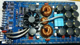
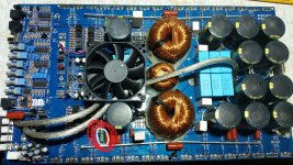
PLEASE, post a good quality photo of the entire board and driver board of audio section.
This, assuming that the ps section is in good working conditions.
This, assuming that the ps section is in good working conditions.
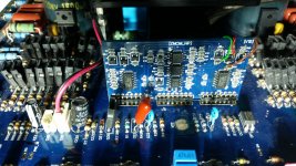
Post a good quality photo of the back of the driver board that shows the wiring that goes to the back of the board.
Do you have rail-rail oscillation?
Do you have rail-rail oscillation?
good rail voltage
Both rail voltages are present. I have a square wave signal on all gate inputs hi side and low side.
Should I be seeing oscillation on hi side gate? Can't get a picture of back side of drive board without removing it.
Both rail voltages are present. I have a square wave signal on all gate inputs hi side and low side.
Should I be seeing oscillation on hi side gate? Can't get a picture of back side of drive board without removing it.
The fan is held in with a couple of screws.
On amps that use a diode on the driver board to supply the high-side B+, you can apply voltage to the high-side with a 9v battery. I'm not sure if that works on the ZNCM boards.
Does the positive high-side supply terminal on the 21844s connect to the corresponding NPN buffer/driver transistors that drive the high-side FETs?
The resistors with a ceramic coating generally don't show much when they fail. They are typically 'flameproof', unlike the resistors with a paint coating.
- Home
- General Interest
- Car Audio
- DS18 spl12.5K