http://sjostromaudio.com/ubc01r0.pdf
I got inspired from someone (can you guess?) to make a DRV134 pcb with built-in regulators, two types of them and the discrete one can handle pretty high input voltage. The design comes right of my head and I haven't tested it in any way.
I got inspired from someone (can you guess?) to make a DRV134 pcb with built-in regulators, two types of them and the discrete one can handle pretty high input voltage. The design comes right of my head and I haven't tested it in any way.
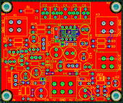
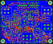
I thought about to have SMD opamps on the solder side along with 0.1% resistors. It's not impossible to fix this. Is there any interest for this? For building a DRV134 solution you'll need three opamps and a dozen of resistors but they have to be with tight tolerances in order to get good performance.
does the DRV need a input offset current feed resistor?
Why exclude the possibility of using balanced input?
Do other balanced opamp drivers fit the pin configuration of the DRV134?
Why exclude the possibility of using balanced input?
Do other balanced opamp drivers fit the pin configuration of the DRV134?
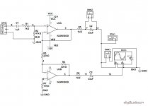
This is a unbalanced to balance driver. If you already have a balanced signal you won't need this converter but I see what you mean. You could use a balanced opamp like OPA1632.
As I see it you can connnect the DRV134 via a cap only. I haven't it though. Anybody who has?
You have a THAT chip which is compatible.
As I see it you can connnect the DRV134 via a cap only. I haven't it though. Anybody who has?
You have a THAT chip which is compatible.
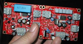
I have debugged the boards now and two errors were but the were minor.
Connector X4 should be +V GND -V, (is +V GND -V, just swap + and -)
Connector X3 should be -OUT (inverting output)
Connector X2 should be +OUT (non-inverting output)
It was right to connect the input coupling cap directly to pin 4 without any pulldown resistors.
Connector X4 should be +V GND -V, (is +V GND -V, just swap + and -)
Connector X3 should be -OUT (inverting output)
Connector X2 should be +OUT (non-inverting output)
It was right to connect the input coupling cap directly to pin 4 without any pulldown resistors.
Will you do another rev or is this the gotcha we need to be aware of?I have debugged the boards now and two errors were but the were minor.
Connector X4 should be +V GND -V, (is +V GND -V, just swap + and -)
Connector X3 should be -OUT (inverting output)
Connector X2 should be +OUT (non-inverting output)
It was right to connect the input coupling cap directly to pin 4 without any pulldown resistors.
Peter
You should beware of this until further notice. The X4 error is really important to notice but I will add a note in each shipment in case someone should miss this.
Eagle files
Do you have this PCB in Eagle format?
http://sjostromaudio.com/ubc01r0.pdf
I got inspired from someone (can you guess?) to make a DRV134 pcb with built-in regulators, two types of them and the discrete one can handle pretty high input voltage. The design comes right of my head and I haven't tested it in any way.
Do you have this PCB in Eagle format?
I bump this question. Any real life experience?Has anybody tested my boards IRL yet?
The problem is fixed.Will you do another rev or is this the gotcha we need to be aware of?
Peter
- Status
- Not open for further replies.
- Home
- Source & Line
- Analog Line Level
- DRV134 pcb