Thanks for the tip john65b. I actually have a couple of 1,000VCT power transformers that I may use to build a direct coupled amp.
Switch tubes.
Lower feedback temporarily.
As in Sanders' amps, the cell is (or ought to be) almost trivial as a load. Takes little power to make loud sounds when done efficiently. So having the cells attached or not shouldn't matter too much. Unless something is amiss.
Ben
I was thinking the same. This amp was used only with a huge Altec 1003B horn I have, so load was always very low. Maybe the extra load caused the tube to start glowing. Need to sort it out.
Thanks
Elias
hmmmm...speaking of feedback, how did you connect the HV supply to the amplifier ground?...Lower feedback temporarily....
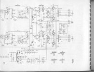
The reason I ask is that according to the schematic the speaker output "COMMON" terminal is not ground, it is actually the feedback pickoff point. The speaker output "4 ohm" terminal is ground.
Not sure if that could be part of your tube heating problem or not.
Attachments
hmmmm...speaking of feedback, how did you connect the HV supply to the amplifier ground?
The reason I ask is that according to the schematic the speaker output "COMMON" terminal is not ground, it is actually the feedback pickoff point. The speaker output "4 ohm" terminal is ground.
Not sure if that could be part of your tube heating problem or not.
I know, but thanks for the reminder. The negative of the bias supply was connected to the 4ohm tap which is tied to the ground.
I believe it may be a weak tube. I'll try to move tubes around to see if it solves the problem. If it does, I know it's the tube. If not, I'll keep looking 🙂
Thanks Bolserst
for the schematic.........................only neg feed back used....I have seen pos & neg feedback used...........an pos feedback used..........never just neg.feedback
I think it this setup not a tube..........good luck
for the schematic.........................only neg feed back used....I have seen pos & neg feedback used...........an pos feedback used..........never just neg.feedback
I think it this setup not a tube..........good luck
I switched the tubes from one channel to the channel I was testing the speaker and all is fine. It looks like one of the tubes was getting weak. I eventually replaced all four with a set of EH 7591 I have and it played beautifully. Loud enough too. Now I'll wire the amp for both channels and install the speakers in my main system.
Any suggestion on how to lower the negative feedback?
Any suggestion on how to lower the negative feedback?
Any suggestion on how to lower the negative feedback?
I'm pretty rusty on tube amps, but that wire coming off the "com" terminal runs to a resistance divider in the cathode of an early tube. Just increase the value of the resistor leading to the cathode resistor. Shouldn't increase instability when you reduce feedback in an amp like that, but I'd keep an eye on things.
Ben
I'm pretty rusty on tube amps, but that wire coming off the "com" terminal runs to a resistance divider in the cathode of an early tube. Just increase the value of the resistor leading to the cathode
I think you will see that Connection coming off the 16 or 8 ohm tap, not the common ground, all else correct...
John I have never seen feedback setup this way ....but the only feedback is coming of the Neg...well that how it looks...right?........learn something every day...
Just increase the value of the resistor leading to the cathode resistor
yes in a nom. setup add more res. well do it!
Just increase the value of the resistor leading to the cathode resistor
yes in a nom. setup add more res. well do it!
Attachments
![478974d1429732053-driving-esl-tube-plates-kx200-02[1].jpg](/community/data/attachments/449/449409-645f1fadcf120f1be42c0ea2a3881c45.jpg?hash=ZF8frc8SDx)
Last edited:
Whoops - you are referring to the schematic Bolsert posted - yes - feedback from com tap is correct...
Posting from an iphone is crazy....yes, the Com in your example is not ground - the 4 ohm tap is grounded.
Most of the tube amps schematics I see have the feedback from the 16 or 8 ohm output taps...I guess they all work the same way if not from COM ground
Posting from an iphone is crazy....yes, the Com in your example is not ground - the 4 ohm tap is grounded.
Most of the tube amps schematics I see have the feedback from the 16 or 8 ohm output taps...I guess they all work the same way if not from COM ground
Last edited:
Yes thanks to mr Bolsert .....for..
all his help...........to Diy nuts........
In the schematic.....that neg is floting ..an well work fine...but most amps I have seen like that..................have pos feedback also...gofig
But adding more res.in the feedback means less feedback not more....most of the time...............where Bolsert............to save us ...
john.....no way can I post from a phone...............good luck with that...if you 15 years old...maybe...hehe
They are singing now...from the plates
Well, I moved both speakers to my main setup. I was planning to use the KX-200 but I could not find a hole to bring all 4 wires from the plates and I did not want to drill one on the amp. So I decided to try a lowly DeWald amp running EL-84s with about 350V on the plates. Not too far from the KX-200 435V. The DeWald has some holes that I could easily pass the wires from the plates thru. Fired up and the panels sound awesome. Even with only ~350V they are pretty loud for my room. They are active x-overed at 250 Hz. I have a McIntosh ML-1C doing below 250Hz.
These panels have been sitting for almost a decade. At first I could hear some slapping of the diaphragm, but eventually it disappeared. Not sure if the bias voltage tighten it up. I'll play for a few days to see if it improves further. Sounds is incredibly detailed and clear, specially the highs.
I attached a couple of pictures. Next step: build an amp dedicated to driving these... I have a thread on the tube forum on that.


Thanks for all the help.
Elias
Well, I moved both speakers to my main setup. I was planning to use the KX-200 but I could not find a hole to bring all 4 wires from the plates and I did not want to drill one on the amp. So I decided to try a lowly DeWald amp running EL-84s with about 350V on the plates. Not too far from the KX-200 435V. The DeWald has some holes that I could easily pass the wires from the plates thru. Fired up and the panels sound awesome. Even with only ~350V they are pretty loud for my room. They are active x-overed at 250 Hz. I have a McIntosh ML-1C doing below 250Hz.
These panels have been sitting for almost a decade. At first I could hear some slapping of the diaphragm, but eventually it disappeared. Not sure if the bias voltage tighten it up. I'll play for a few days to see if it improves further. Sounds is incredibly detailed and clear, specially the highs.
I attached a couple of pictures. Next step: build an amp dedicated to driving these... I have a thread on the tube forum on that.
Thanks for all the help.
Elias
Hi Mazur,
I was digging around the web on this topic, as I was intrigued by your experimentation with DD tube stators. Found this interesting link.
Twin OTL - Twinstatic Audio
Cool mod of a Acoustat Servo Charge amp, and this companies bottom amp (expand photo) shows a high voltage type tube.
I'd be interested to see how your projects turn out.
Bentoronto, do you still have the schematic for your DD amp? I understand you sold it a while back, but was it reliable, etc? Photos? Thanks.
Neil
As Tyu mentioned, increasing resistance of the feedback resistors (R65/R66) will reduce the amount of feedback. Generally you will also want to adjust the compensation capacitor(C23/C24) value to optimize high frequency response/stability.Any suggestion on how to lower the negative feedback?
Note also that the parallel combination of the feedback resistors and the cathode resistors(R39/R40) defines the voltage drop from ground that provides the bias voltage and operating point for the phase splitter. So, changing the value of the feedback resistor will slightly change the operating point of the DC coupled phase splitter. To keep the operating point unchanged, you would need to adjust the cathode resistors(R39/R40) down in value slightly as you adjust the feedback resistor up in value to lower feedback.
You would like to have the operating point of the phase splitter set so that the output capability for positive and negative peaks of the audio signal are limited by the output tube clipping, not phase splitter clipper. Looking at the values in the circuit, I don't think the operating point will be dramatically shifted if the feedback resistor is increased. But, it is something to keep in mind when adjusting resistor values around DC coupled phase splitter circuits.
Hi Mazur,
I was digging around the web on this topic, as I was intrigued by your experimentation with DD tube stators. Found this interesting link.
Twin OTL - Twinstatic Audio
Cool mod of a Acoustat Servo Charge amp, and this companies bottom amp (expand photo) shows a high voltage type tube.
I'd be interested to see how your projects turn out.
Bentoronto, do you still have the schematic for your DD amp? I understand you sold it a while back, but was it reliable, etc? Photos? Thanks.
Neil
Hi Neil.
Interesting (but expensive) set of amps. I finally connected my Fisher KX-200 yesterday and it sounded amazing. Even my wife commented on how much better it sounded than my previous system 😱😎 . And my previous setup was pretty nice: a huge Altec 1003b setup with a supertweeter. The KX-200 has about 435V on the plates, so it's almost 900V voltage swing. Sounds pretty loud. Very clear and detailed. The Altec 1003B made drums sound awesome, but these guys driven from the plates brought the drum set to my living room. Amazing.

Overall, I think it was such an easy thing to do, given of course if you have worked with tubes and HV before. If you have a nice tube amp 30 to 60 watts with maybe 400+ VDC on the plates, give it a try.
I'm planning to build a dedicated amp to drive them, much like the ones shown on your link.
Thanks.
Elias
As Tyu mentioned, increasing resistance of the feedback resistors (R65/R66) will reduce the amount of feedback. Generally you will also want to adjust the compensation capacitor(C23/C24) value to optimize high frequency response/stability.
Note also that the parallel combination of the feedback resistors and the cathode resistors(R39/R40) defines the voltage drop from ground that provides the bias voltage and operating point for the phase splitter. So, changing the value of the feedback resistor will slightly change the operating point of the DC coupled phase splitter. To keep the operating point unchanged, you would need to adjust the cathode resistors(R39/R40) down in value slightly as you adjust the feedback resistor up in value to lower feedback.
You would like to have the operating point of the phase splitter set so that the output capability for positive and negative peaks of the audio signal are limited by the output tube clipping, not phase splitter clipper. Looking at the values in the circuit, I don't think the operating point will be dramatically shifted if the feedback resistor is increased. But, it is something to keep in mind when adjusting resistor values around DC coupled phase splitter circuits.
Thanks for the suggestions. What improvement do you think I'll get but lowering the NF? My fear is that it will increase the distortion and make it a bit less linear.
Thanks
Elias
Another question: when driving a typical 8 ohms speaker, the type of tube and of course the transformer makes a big difference on the sound. So different tubes have different sonic characteristics. When driving the ESL from the plates, does that difference also plays out. In other words, different tubes will sound different?
Only the tube made in Russia with the secret transmitter inside make a difference (only half kidding).
BTW, I suppose there should be ordinary 4, 8, or 16 ohm resistors connected in order to give the amp the kind of load it expects to see. Resistors have to be handle the full power of the amp during sine tests and some fraction of that on music.
(I'll look for a schematic for my old DD amp. Similar to AA/Sanders publication.)
Ben
Only the tube made in Russia with the secret transmitter inside make a difference (only half kidding).
BTW, I suppose there should be ordinary 4, 8, or 16 ohm resistors connected in order to give the amp the kind of load it expects to see. Resistors have to be handle the full power of the amp during sine tests and some fraction of that on music.
(I'll look for a schematic for my old DD amp. Similar to AA/Sanders publication.)
Ben
You are not kidding at all 🙂 Yesterday I answered my own question. As I was doing some critical listening I noticed that the Fisher just did not sound as good as the "el cheapo" DeWald. The Fisher has Russian EH 7591s and the DeWald has Raytheon 6BQ5s. The difference in sound quality between them was noticeable. I switched back and the DeWald does sound better. I know there many variables involved (circuit topology, etc) but I guess I could say the 6BQ5 did sound better than the Russian 7591s. Next I got try the Fisher with some vintage 7591s I have.
Funny thing is, the DeWald always sounded pretty crappy on my horns because of the really cheap output transformers it has. Took the tranny out of the picture, sounded pretty good 😎
BTW, I'd love to see the schematic for your DD amp.
Thanks
Elias
- Status
- Not open for further replies.
- Home
- Loudspeakers
- Planars & Exotics
- Driving ESL from tube plates