Hi,
I'm designing a circuit to drive a PCM4202 ADC from a single-ended source. What I want to do is to use a separate ADC for each side of a normal pro-audio TRS input. My thoughts are that it'll give me slightly better SINAD than using the one converter (after subtracting the digital outputs), with the benefit of allowing me to plug a stereo source in should I want.
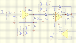
So to do this, I'm working with the PCM4202 data sheet circuit (which uses an OPA1632). I've simply grounded one side of the differential input, and am driving the other side with my single-ended source (via a buffer, to increase the input impedance and allow me to switch the gain to account for +4dBu and -10dBV signals. I've included a screen-grap of the circuit for reference.
Only the circuit doesn't work terribly well with unbalanced signals, on account of the 40.2 ohm resistors on the output of the OPA1632. What do these resistors accomplish? Are they there to limit current into the ADC? Why are they such a bloody weird value anyway? The only way to get the output of this buffer circuit to be balanced with a single-ended input is to remove them.
If I can't ditch the resistors, I guess I need an additional stage beforehand to convert the single-ended signal to differential, before feeding it into the differential driver.
So what's the usual scheme for driving one of these differential input ADCs from a single ended source, anyway?
I'm designing a circuit to drive a PCM4202 ADC from a single-ended source. What I want to do is to use a separate ADC for each side of a normal pro-audio TRS input. My thoughts are that it'll give me slightly better SINAD than using the one converter (after subtracting the digital outputs), with the benefit of allowing me to plug a stereo source in should I want.
So to do this, I'm working with the PCM4202 data sheet circuit (which uses an OPA1632). I've simply grounded one side of the differential input, and am driving the other side with my single-ended source (via a buffer, to increase the input impedance and allow me to switch the gain to account for +4dBu and -10dBV signals. I've included a screen-grap of the circuit for reference.
Only the circuit doesn't work terribly well with unbalanced signals, on account of the 40.2 ohm resistors on the output of the OPA1632. What do these resistors accomplish? Are they there to limit current into the ADC? Why are they such a bloody weird value anyway? The only way to get the output of this buffer circuit to be balanced with a single-ended input is to remove them.
If I can't ditch the resistors, I guess I need an additional stage beforehand to convert the single-ended signal to differential, before feeding it into the differential driver.
So what's the usual scheme for driving one of these differential input ADCs from a single ended source, anyway?
Attachments
I would say you should use an SSM2142 balanced line driver, either before the OPA1632 or in place of it. Very simple to use & extremely transparent sound.
Suzy,
The capacitor at the output of the diff amp is there to provide a bucket full of electrons for the ADC. ADC's work these days by filling an internal capacitor with charge. This charge is then selectively distributed to a weighted string of caps (32, 16, 8, 4, etc...) in order to convert to a number. The cap is a good thing.
The 40 ohm resistors are put there to to keep the caps from upsetting the amplifier. Op-amps do not like their outputs to be connected DIRECTLY to a ground refereenced cap... it causes instabilty. The value of the 40 Ohm resistors is not real critical... 20 to 100 OHM is typical.
If you want to look for problems... what is the amp driving the reference node of the 1632 input all about? Where is its signal coming from?
Also... the whole point to differential drive is cancel even harmonics... why go single ended to the convertor?
Yes, I realised later that the amp wasn't happy driving the load capacitance, so I'll leave the output resistors alone. If I put a second opamp after the first, with a gain of -1, it behaves itself quite nicely.
The signal driving the Vcom input on the OPA1632 is the 2.5V Vcom output on the PCM4202. The data sheet doesn't specify the output impedance of this line, and suggests buffering it, so who am I to argue.
This circuit is half the input - I'm using a second input buffer, and a second ADC (actually the other side of the same stereo ADC), for the other side of the balanced line.
I plan to do the common-mode cancellation digitally. This will (I hope!) allow me to squeeze a few more dB dynamic range out of the ADC (effectively adding a bit). It also makes the input more flexible, as I can use the same TRS connector for either balanced mono or unbalanced stereo. That's also what the link is for - it allows me to select either 0dB or -12dB gain, to suit +4dBu and -10dBV levels. The only downside is that there's twice as many parts, but that's not a big problem.
Well,
Kick this around. When you use the PCM differentially, it capable of digitizing a 6 Volt positive OR a 6 Volt negative signal... this is a total signal excursion of 12 Volts. When you tie one input of the PCM to ground, you are only able to see the positive excursion of the signal. In other words, you have effectively cut the dynamic range in half. Think about it... the ADC will never produce half of the numbers in its range.
Now... doing this twice will indeed double the resolution. So... 2 times 1/2 equals one... which is where you started. On paper, you have the same thing as a single PCM configured traditionally... differentially. What you have lost is the common mode rejection (even order distortion) and a few other goodies.
Sorry... but this violates the "No Free Lunch" rule of engineering. When lunch is free... you'll probably see a wookee there first.
🙁
EDIT: Keep in mind, without seeing the whole circuit, I might be missing something here. Are you applying a full differential signal to the PCM? Are both outputs of the 1632 feeding the diff' pair inputs on the PCM?
I'm rolling it as I go, so there isn't a whole circuit yet.
I've attached a pdf of the input stage for both sides of a balanced pair (or stereo source).
It's not a free lunch at all - it costs twice the number of ADCs, and twice the number of opamps per channel.
Each side of the balanced pair is sampled separately, using the whole resolution of the ADC. The input swing is the full range that the converter can deal with.
After digitising, the two signals are subtracted digitally. The result of a 24 bit subtract is 25 bits, and all 25 of those bits are used.
So if it's only quantisation errors that are limiting things (and it won't be) the result will be a 6dB improvement in dynamic range.
Page 22 of the PCM1794A data sheet has a similar topology, only for a DAC, where each side of a stereo DAC drives one signal in a balanced system. They claim a 3dB improvement in dynamic range (to a pretty impressive 132dB).
I have no idea whether I'll be able to get any improvement in dynamic range on a PCM4202, but I figure it's worth a try, especially as it doesn't preclude the use of each side of the balanced input independently (for stereo signals).
Attachments
suzyj said:
Only the circuit doesn't work terribly well with unbalanced signals, on account of the 40.2 ohm resistors on the output of the OPA1632. What do these resistors accomplish? Are they there to limit current into the ADC? Why are they such a bloody weird value anyway? The only way to get the output of this buffer circuit to be balanced with a single-ended input is to remove them.
Thread resurrection.
Basically I'm having the same problem described here and with the same ADC.
The schematic is as shown on page 6 of the following data sheet.
http://focus.ti.com/lit/ds/symlink/opa1632.pdf
If I apply a single ended signal to R1 with R2 grounded, then the voltage measured before R5 and R6 is identical. However the voltage measured after R5 and R6 differs.
For example the peak to peak output after R6 = 0.8V, but the output after R5 = 0.64.
I thought this could be something to do with resistor matching, however all are 1% and I've got two channels constructed, each behave in exactly the same way.
Does anyone have any idea what's going on here? As I find it most puzzling.
Thanks in advance
Matt.
Re: Re: Driving differential ADC with single-ended source
Matt,
This is hard to visualise, I'll see if I can explain - and get
it right 🙂
If both OP's are forced to be equal +/- then there must be a
common mode shift at the +/- IP's if one IP R is grounded,
otherwise the +/- IP's would not follow each other.
Here's a simple way to visualise it. Draw an OPA1632 with 1k IP R's
and 1k FB R's. The gain is 1.
So for +1V swing on the + 1k IP R, each OP must swing + and -
0.5V to satisfy gain criterion. As such + IP (at opamp) will shift up
+0.25V.
+ and - IP's follow so - IP will also shift up +0.25V.
You can see now that current through FB R's is not equal and
opposite, so any point other than the actual opamp OP will see
an imbalance.
cheers
Terry
5th element said:
Thread resurrection.
Basically I'm having the same problem described here and with the same ADC.
The schematic is as shown on page 6 of the following data sheet.
http://focus.ti.com/lit/ds/symlink/opa1632.pdf
If I apply a single ended signal to R1 with R2 grounded, then the voltage measured before R5 and R6 is identical. However the voltage measured after R5 and R6 differs.
For example the peak to peak output after R6 = 0.8V, but the output after R5 = 0.64.
I thought this could be something to do with resistor matching, however all are 1% and I've got two channels constructed, each behave in exactly the same way.
Does anyone have any idea what's going on here? As I find it most puzzling.
Thanks in advance
Matt.
Matt,
This is hard to visualise, I'll see if I can explain - and get
it right 🙂
If both OP's are forced to be equal +/- then there must be a
common mode shift at the +/- IP's if one IP R is grounded,
otherwise the +/- IP's would not follow each other.
Here's a simple way to visualise it. Draw an OPA1632 with 1k IP R's
and 1k FB R's. The gain is 1.
So for +1V swing on the + 1k IP R, each OP must swing + and -
0.5V to satisfy gain criterion. As such + IP (at opamp) will shift up
+0.25V.
+ and - IP's follow so - IP will also shift up +0.25V.
You can see now that current through FB R's is not equal and
opposite, so any point other than the actual opamp OP will see
an imbalance.
cheers
Terry
So for them to be equal and opposite, -IP would have to be -0.25V, but it's not, hence the deviation after the load resistors.
So you're saying that the differential follows normal opamp laws, except that the output swing is considered as the total swing from the +ve to -ve output.
Hence 1 V on +IP. -0.5V on -OP and +0.5V on +OP.
1V/1k = 1mA. The feedback resistor must develop 1mA so that they are balanced requiring that 1 Volt is present. But there's only 0.5. Are you saying we shift both inputs up by 0.25 Volts and as they are 'summed' we add them together and hence gain the additional 0.5 volts we need to satisfy opamp laws?
In my instance if I apply 4.7Vp-p, I'd expect to get 0.63Vp-p after the differential.
270/1000= a gain of 0.27. 4.7*0.27 = 1.269Vp-p. This we half to satisfy the gain so we get 0.63Vp-p each.
There is a loss here of 0.63V.
4.7/1000 = 4.7mA, so 4.7mA should be developed across the feedback resistor. We've only got half of this, so you're saying we get a common mode shift here of 0.63Vp-p so that it balances out?
If this is correct is not hugely important -.- what's good to know is that the circuit is operating as intended.
Interestingly enough it appears to function without any problems, even though the +ve and -ve inputs on the ADC are not equal.
The only problem I have with the design is that it's rather noisy, however I don't think this is responsible for that, as it's just as noisy with both the inputs disconnected.
And ill be damned if I know what the cause is, but that's for another thread.
- Status
- Not open for further replies.
- Home
- Source & Line
- Digital Line Level
- Driving differential ADC with single-ended source