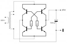
I was searching the net for alternative rectifiers and found Herbert Rutgers webiste with a document showing this diagram with a rectifier bridge made of transistors:

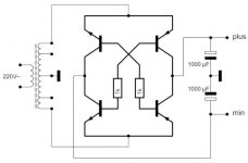
I made a crude simulation of the center tapped version which you can see online here. Seems to work well. But I could not find any other evidence of this circuit online.
Would this kind of rectifier be good for audio PSUs? Also I don't know how to calculate the values of the two resistors in the middle...?
Attachments
Seems to work well. But I could not find any other evidence of this circuit online.
Would this kind of rectifier be good for audio PSUs? Also I don't know how to calculate the values of the two resistors in the middle...?
It is well suited to Ge transistors. Modern Si transistors have a Veb breakdown voltage of 5.5V to 10V, and this will make the circuit useless if the peak AC voltage exceeds that limit.
Ge also allows very low Vcesat voltages.
The resistors need to provide enough base current to keep the transistors saturated for the max peak charging current of the cap
Last edited:
Modern Si transistors have a Veb breakdown voltage of 5.5V to 10V, and this will make the circuit useless if the peak AC voltage exceeds that limit.
I would also be wary of sticking 1000uf on transistor collectors.
Its pretty much a short on power up. Unless base resistor limits current.
Diodes are capable of high currents for short periods so do the job well.