Hello all,
I hope everyone is doing well during these times.
This is my first post and a call for help, so I appreciate everyone`s input and wisdom greatly.
I have built my first ever tube amp, a SE design from Popovich`s book on tube amps, and build a power supply for it from scratch. Now I wasn’t 100% sure of the power supply for this amp, but the idea was to supply all voltages from separate windings, with bridge rectifiers for each circuit, as they are cheap and available. Upon the turn on, to have only heaters and negative bias on, and then via separate switch B+.
I fed 2Vpp 500Hz sinewave signal from the signal generator to the amp, after the preamplifier stage it gets to 31Vpp, looking all good, after passing through one half of 5687 it is amplified to 50Vpp, but with the top of the sinewave well flattened.
While testing voltages without any tubes in the amp, the voltages vary quite a lot, but with all tubes in voltages drop closer to intended values +-10%.
And now the part that throws me off, is the driver and output stages. The driver tube`s grid has the correct negative voltage and seems to be all fine, but the cathode of the driver tube has reversed polarity, instead of negative as in the schematic I get the same voltage positive? Even it is connected to negative voltage?? which effectively makes output tube`s grid positive 😕 Why does this happen? I have a feeling that I must`ve got something fundamentally wrong here, but after the amount of time spent which is equal to wanting to smash this thing to pieces, I can't really find the answer .
.
I tried to troubleshoot with the test lamp to see if there are any shorts, which there weren’t any. I double-checked all solder joints etc. and all seem sturdy, checked all the connections. I did try to change up a bias and driver`s power supply a little (version 2) where driver plate and negative bias were fed from the voltage doubler symmetrical circuit, to see if this makes any difference, but nothing. Did some other various changes to the power supply, but the result is the same,
I would really appreciate any help to get some output here.
Thanks,
Karolis
I hope everyone is doing well during these times.
This is my first post and a call for help, so I appreciate everyone`s input and wisdom greatly.
I have built my first ever tube amp, a SE design from Popovich`s book on tube amps, and build a power supply for it from scratch. Now I wasn’t 100% sure of the power supply for this amp, but the idea was to supply all voltages from separate windings, with bridge rectifiers for each circuit, as they are cheap and available. Upon the turn on, to have only heaters and negative bias on, and then via separate switch B+.
I fed 2Vpp 500Hz sinewave signal from the signal generator to the amp, after the preamplifier stage it gets to 31Vpp, looking all good, after passing through one half of 5687 it is amplified to 50Vpp, but with the top of the sinewave well flattened.
While testing voltages without any tubes in the amp, the voltages vary quite a lot, but with all tubes in voltages drop closer to intended values +-10%.
And now the part that throws me off, is the driver and output stages. The driver tube`s grid has the correct negative voltage and seems to be all fine, but the cathode of the driver tube has reversed polarity, instead of negative as in the schematic I get the same voltage positive? Even it is connected to negative voltage?? which effectively makes output tube`s grid positive 😕 Why does this happen? I have a feeling that I must`ve got something fundamentally wrong here, but after the amount of time spent which is equal to wanting to smash this thing to pieces, I can't really find the answer
. I tried to troubleshoot with the test lamp to see if there are any shorts, which there weren’t any. I double-checked all solder joints etc. and all seem sturdy, checked all the connections. I did try to change up a bias and driver`s power supply a little (version 2) where driver plate and negative bias were fed from the voltage doubler symmetrical circuit, to see if this makes any difference, but nothing. Did some other various changes to the power supply, but the result is the same,
I would really appreciate any help to get some output here.
Thanks,
Karolis
PHP:
Attachments
Not a (direct) explanation for your measurements but something in the schematic is not right.
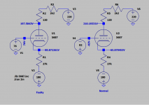
The anode current of the driver (5687) is given as 10 mA, which almost corresponds with the B+ of 220 V, the anode voltage of 195 V, and the values of the two resistors in the anode lead. The calculated anode current is: I = V / R = (220 - 195) / (2200 + 120) = 10.8 mA.
But the voltage drop over the cathode resistor of 27K is given as 180 - 70 = 110 V. The current through the cathode resistor than would have to be: I = V / R = 110 / 27K = 4.1 mA.
In real life, the anode and cathode current should ofcourse be identical.
Something else: If there really was +70 V on the grid of the 6C33C-B, than it must have passed an enormous amount of currrent so it must have been very 'unhappy'.
The plate current = cathode current =4.2mA when grid is -82V
The plate current = cathode current =9.7mA when grid is 76V
or about 10mA is measured under fault condition? I see it's handwritten so not sure what is it refereed to exactly.
The plate current = cathode current =9.7mA when grid is 76V
or about 10mA is measured under fault condition? I see it's handwritten so not sure what is it refereed to exactly.
The "10 mA" looks indeed handwritten but the indicated voltages (+220V, 195V, -70V, and -180V) and the resistor values look original. So even without the handwritten "10 mA" there is something not right in the schematic.
I'm not so sure if that is the only mistake in the schematic.
The grid voltage of the driver is indicated as -85 V. The current through the three resistors for this bias is: I = V / R = 180 / 188K = 0.957 mA. That would mean that the voltage at the connection of the 68K resistor and the 20K pot would be: V = I x R = 0.957 x 68K = -65,1 V. It would also mean that the voltage at the connection of the 20K pot and the 100K resistor would be: V = I x R = 0.957 x 88K = -84,3 V. But these results seem unrealistic. The range of the 20K pot for adjusting the bias would lie between -65.1 V and -84,3 V so it would even be impossible to adjust for -85V since that voltage is outside the range of the pot. More realistic would be that the required grid voltage lies somewhere in the middle of the range of the pot.
The grid voltage of the driver is indicated as -85 V. The current through the three resistors for this bias is: I = V / R = 180 / 188K = 0.957 mA. That would mean that the voltage at the connection of the 68K resistor and the 20K pot would be: V = I x R = 0.957 x 68K = -65,1 V. It would also mean that the voltage at the connection of the 20K pot and the 100K resistor would be: V = I x R = 0.957 x 88K = -84,3 V. But these results seem unrealistic. The range of the 20K pot for adjusting the bias would lie between -65.1 V and -84,3 V so it would even be impossible to adjust for -85V since that voltage is outside the range of the pot. More realistic would be that the required grid voltage lies somewhere in the middle of the range of the pot.
Last edited:
This will happen if you have +76V on grid of last 5687 section, check the grid voltage again after all on. Coupling cap 0.33uf maybe leaky,
The last section of the 5687 grid has negative voltage, it does adjust to -85 and the range is good, variac was slightly lower than actual mains are, so -85 was close to the top.
It actually adjusts to -85, the range was kind of good, all negative voltages appear fine, but except this leg with 27k resistor, like the voltage becomes positive on the other side of the resistor 😕
there were actually some misprints, the pin numbers for 5687 were wrong, 8 was shown as cathode but in the datasheet, it is actually the heater center tap and 6 on the schematic is plate but on datasheet it is cathode... just wondering if the actual values then are fine
there were actually some misprints, the pin numbers for 5687 were wrong, 8 was shown as cathode but in the datasheet, it is actually the heater center tap and 6 on the schematic is plate but on datasheet it is cathode... just wondering if the actual values then are fine
If the variac was slightly lower, the indicated -180 V was also slightly lower. That would mean that according to the resistor values in the schematic the grid voltage of -85 V would be even further outside the range of the 20K pot. At -176 V (like is handwritten in the schematic) the range of the 20K pot would be -63.7 to -82.4 V.
But what about the 6C33C-B? You wrote that you had all the tubes in. If there really was +70 V on the grid of the 6C33C-B than you must have noticed that right away.
Addition: In itself, the voltage at the cathode could rise to 70 V if the current through the 27K cathode resistor is high enough. With -180 V the current would than have to be: I = V / R = (180 + 70) / 27K = 9.26 mA. I write 'in itself' because such a large current is difficult to combine with the way the driver seems to be biased. And again, I would expect the 6C33C-B starting to die right away with +70 V on its grid.
Last edited:
Hi, so when you get -85V on grid, when B+ is off, no doubt, but what voltage on same grid after B+ is on?
Last edited:
I think there is something wrong with the 6C33.Probably the voltages are ok without that tube in place.
Mona
Mona
If +80v is coming from a faulty 6c33c, the plate voltage of 5687 would be way out as little current flows through the tube.
If you call an anode voltage of close to the B+ of +220 V instead of being around 195 V (or 210 V) "way out", than I agree.
The most likely explanation for me is that TS measured the +70 V with a meter with reversed polarity, but I also suspect that TS thought of this already and checked this more than once.
Mona's suggestion also seems a plausible explanation to me. If we are talking about a stereo amp than two identical wiring mistakes seem more likely than an identical fault inside the two 6C33C-B's. But I find it hard to imagine what kind of wiring mistake this could be. The only source for a high enough positive voltage is the anode (pin). I would think that a dead short would give a much higher voltage on the grid than +70 V.
Leaking coupling is a very common problem, depending on climatic condition. You need only 12k resistance between plate and cathode to give +80V, why needs higher? To prove that 27k cathode smoking or not?
I don't really know what you mean. I assume you are talking about the driver but how do you arrive at 12K? And leaking coupling (which for now I understand as a leakage resistance of 12K inside the driver and/or at its base) on this scale is a very common problem? Do you have a source for that statement?
And what would I, or somebody else in this thread, be trying to prove according to you? What's the smoking about?
I wish we would hear from TS if this is a stereo amplifier, and if so, if the same problem occurs in both channels.
And what would I, or somebody else in this thread, be trying to prove according to you? What's the smoking about?
I wish we would hear from TS if this is a stereo amplifier, and if so, if the same problem occurs in both channels.
Last edited:
I'm reflecting on your comment of dead shot, so I think no need for dead shot, 12k short inside or outside will give +80V on cathode. It should read coupling capacitor leakage.
I still wait for his reply what is going on with bias supply voltage measuring, did you all hear him says it is -85V on grid on all conditions? If that is so I retract my explanation for his problem.
I still wait for his reply what is going on with bias supply voltage measuring, did you all hear him says it is -85V on grid on all conditions? If that is so I retract my explanation for his problem.
OK, I understand you now. But I didn't write that a dead short is needed or likely. I wrote that I find a dead short in or around the 6C33C-B hard to imagine.
Last edited:
About 12k resistor it was last section of 5687 I refer to, when the tube is shunted either inside or outside.
The leakage cap I have ordered before from US, but made in France I returned all, it measured a fixed resistance up to only a few Megs. A good one would just reach 30Meg and maintained this value for many hours if not days. Unfortunately the shop refused to refund saying my method is incorrect, since than I never use that brand, Solen is still very good in my country. Watch out for climatic condition some mentioned in their products due to particular type of dialectic used.
Search my post you may also find a few threads I posted about leaking capacitor. E.g in guitar amp it was normal during standby but fault in normal operation, an expansive new coupling found leaking.
Last edited:
- Home
- Amplifiers
- Tubes / Valves
- Driver Stage Issue for SE Amp