Yes, you are right, the 1,81mA is without the current from the 100k.I think that in the schematic of Mona the current through the 6SN7 has to be 1.53 mA, so the indicated 1.81 mA must be a 'left over' from the schematic of Koonw.
I(R5) = V(R5) / R5 = 2.454 / 470 = 5.22 mA
I(R1 + R31) = V(R1 + R31) / (R1 + R31) = (255.406 – 2.454) / 1330000 = 0.19 mA
I(R4) = V(R4) / R4 = (353.431 – 2.454) / 100000 = 3.5 mA
I(6SN7) = I(R5) – I(R1 + R31) – I(R4) = 5.22 – 0.19 – 3.5 = 1.53 mA
This outcome fits with
I(R2) = I(6SN7) + I(R1 + R31) = 1.53 + 0.19 = 1.72 mA
and
I(R2) = V(R2) / R2 = (371.87 – 255.406) / 68000 = 1.71 mA
I didn't look at it, that's why the text is rather far from the line where the current flows.
Mona
You can use a lower OT Z of 2.5k with additional modifications, but preferable use a tube with high dissipation say 30W 6L6GC/6LGT :
1. Increase Schade or shunt feedback (Change R4 from 1.5Meg to 1Meg)
2. Add Cathode feedback (wire output tube cathode to output instead of ground). Doing this reversed the output phase and you can not use NFB but that is ok as I modified the driver to use more local feedback instead to reduce distortion. You can read more about Schade feedback in this thread:
Schade Feedback
I can post the simulation file is you want it.
Koonw, do you still have the lspice file? If you can send me I would appreciate so I can verify the sims in comparison with the job. Thanks

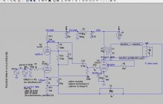
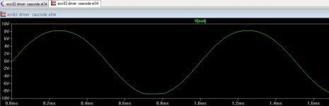
Based on a project appeared on an old italian electronics magazine (in the nineties) and then the same schematic revisited by mr. Bianchini I ran the sim using the ECC82 (it should fit well enough for the cascode). The results through the triode mode seem good, bringing a low THD and an output pwr(rms) of 4.4W per channel. Maybe in U.L. it should settle down at about 6W.
I wonder if this route is a viable alternative, because swapping to 6SN7 would mean to change the noval tube sockets and.at present I don't have the SN tubes.
I wonder if this route is a viable alternative, because swapping to 6SN7 would mean to change the noval tube sockets and.at present I don't have the SN tubes.
Attachments
Noval exact equivalent of 6SN7 is 6CG7 or 6FQ7. Their electrical characteristics are exactly the same.
ECC82 (12AU7) is not the same electrically as 6SN7. Close, but not the same.
ECC82 (12AU7) is not the same electrically as 6SN7. Close, but not the same.
Ah ok, I've just seen today the equivalent 9-pin tube 6CG7 only with a pair of W less of the 6SN7 (but with the currents in role I don't think it's a problem).
Yes, obvioulsy the ECC82 belongs to another tube's family and maybe it's not appriopriate.
Yes, obvioulsy the ECC82 belongs to another tube's family and maybe it's not appriopriate.
ECC82 (12AU7) would certainly work. It might introduce a bit more THD, though. Sometimes this can be a good thing if the additional THD causes some distortion cancellation between stages. One can't always count on this, though.
After various sims on Ltspice and comparing with some circuits (including particular ideas on Tubecad) with the 6n2p from the beginning I tried to assemble everything according to constant-current-draw amplifier (CCDA) circuits, bringing to a good results in terms of THD with use of the EL34 in triode mode.
The main and most important thing I've had to use though was the elevated heater for the preamp tubes, divided each in two sections (elev/no elev).
In any case as a first listen after turning on the amp was the total quiet from the speakers and the sound seems ok even though a little different from the other SE 6SJ7/KT66 I have.
I mean a little more bass but the other was maybe more "open" and more full in mids/highs. The amp is not fully assembled and I still have to check voltages, soldering and paths etc. Furthermore as for now I omitted the NFB at cathode, beacuse the sims didn't worsen the results by it, but I realize that it could somehow influence the sonics.
As first attempt (experimentation) it's not bad overall, if someone has a suggestion about it I'd appreciate also for any advise on next step.
Attachments
Not sure how involved you want to get but V6 of Linear Audio has an article by Frank Blöhbaum with a circuit for the 6P3S and there's a follow-up article in V8. You are already using the output tube and some of his other circuits use three stages , like yours, with a cathode follower as the driver.
More parts in his and it needs a bias supply as well but if you're build is open enough for changes it might be worth having a look at the articles. Just a thought.
More parts in his and it needs a bias supply as well but if you're build is open enough for changes it might be worth having a look at the articles. Just a thought.
Thanks for the hint Hearinspace, but I can see the article isn't for a free read.
I found that there is a mention on Merlin's book I already have, anyway it would be a thing to get in deep about pentodes in general
I found that there is a mention on Merlin's book I already have, anyway it would be a thing to get in deep about pentodes in general
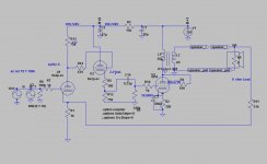
About the driver's circut, as for as I undestood B+ on g2 has to be half of B+ going to p1 through the resistor R13, in order to obtain equal currents flowing through both triodes U1 and U2, independently from signal amplitude on V(in) (constant current).
In such this way, being the signal on U1 superimposed to the dc voltage in anti-phase to that on U2, the resulting noise from the PSU is cancealed out and there is a PSRR improvement.
But by running the sims things seem to be a little different: the B+ on g2 lies instead between 2/3B+ and 1/2B+ for best results.
I have a doubt about this difference, that maybe it depends on the nature of simulation (mathematical approximations, etc.) or it's something else I didn't get as for now.
- Home
- Amplifiers
- Tubes / Valves
- Driver stage for 6p3s SE amplifier