The calculator agrees with AllenB's values for 8 ohm impedance and 6 dB of attenuation i.e. Rs = 4 ohm and Rp = 8 ohm - so can be trusted.
For a nominal impedance of 8 ohm and an attenuation of 10dB, the calculator gives Rs = 5.47 ohm and Rp = 3.7 ohm. In practice, you would choose the nearest standard resistor values to those i.e. 5.6 and 3.9 ohm respectively - again agreeing with AllenB's estimates.
Did not dispute that at all. It is using 8 Ohm driver. Actual measured resistance is 6.6 Ohm. That is what I placed in the calculator. There is still something more about the results I need to understand.
Resistance (the opposition to direct current) does not equal impedance (the opposition to alternating current).
Your 6.6 ohm resistance driver has nominally 8 ohm impedance and that's the value you should use in the L pad calculator - as I/we did.
Your 6.6 ohm resistance driver has nominally 8 ohm impedance and that's the value you should use in the L pad calculator - as I/we did.
Impedance varies with frequency. You cannot use a number and expect it to be right in all ways. 8 ohms is a reasonable average, 6.6 ohms is more of a minimum. If you want it even more accurate you might look at using a simulator 😉
Perhaps you should just look at the table which appears below the calculator.There is still something more about the results I need to understand.
Simply choose the row which corresponds to Z = 8 ohm and A = the number of dB of attenuation you want.
The value of the series resistor R1 and of the parallel resistor R2, in ohms, cannot then be mistaken.
If that doesn't help you understand, please explain your difficuty.
"If that doesn't help you understand, please explain your difficuty."
It was the Z total of 15.96 and or the single resistor value.
I used 8 ohm and 6 db for the attenuation. These plugged in simplified the math and I now see the total calculation for z. Using 6.6 resulted in too many fractions to see it clearly.
Again this conversation helped and it is keeping it simple.
I honestly do not know if doing this will achieve the results I am looking/listening for but, we will see.
Thanks again.
So, just to confirm, for 8 ohm and -6 dB the L pad should consist of a 4 ohm series resistor and an 8 ohm parallel resistor.It was the Z total of 15.96 and or the single resistor value. I used 8 ohm and 6 db for the attenuation.
You can simply ignore the Z total and single resistor values when designing for an L pad.
Let us know if this knowledge helps solve your problem.
P.S. Ceramic wire-wound resistors rated at 10 W will do the job just fine and are not too expensive - so you can probably afford to order some alternative values to suit different degrees of attenuation and facilitate experimentation.
Go for ones like the ceramic resistors selectable from the pull-down menu here: Ceramic Resistors
Go for ones like the ceramic resistors selectable from the pull-down menu here: Ceramic Resistors
P.P.S. As Ralf eluded to earlier, there is a question mark hanging over whether your crossover circuit is designed correctly.
A mistake there could account for a poor frequency balance.
If you should care to attach a drawing of your crossover schematic, indicating the values of inductors and capacitors you've used, we could at least determine if the basic layout is sound.
A mistake there could account for a poor frequency balance.
If you should care to attach a drawing of your crossover schematic, indicating the values of inductors and capacitors you've used, we could at least determine if the basic layout is sound.
"As Ralf eluded to earlier, there is a question mark hanging over whether your crossover circuit is designed correctly.
A mistake there could account for a poor frequency balance."
"If you should care to attach a drawing of your crossover schematic, indicating the values of inductors and capacitors you've used, we could at least determine if the basic layout is sound."
Yes there is a question of the crossover and it certainly is a factor in Freq balance.
The crossover is existing from the original build. I did replace all the electrolytic with good quality film caps. When that delivered horrendous results I replaced the 10 inch driver with Dayton Audio DC250-8 10" Classic Woofer
I replaced the 6" with PRO-GM 6.5" Mid-Range Loudspeaker 480 Watts 8-Ohm (1 Speaker)
– ds18caraudio
After this and using for a good couple months decided to pursue more bottom as the Woofer was lower in volume then the 6 in.
Now some may be asking why I would do this. The drivers fit perfectly and were very inexpensive. I paid more for the capacitors.
The problem is there are no known specs for the existing crossover. Mostly the specs for the inductors are unknown.
Part of this challenge to myself is can I improve the sound of these factory speakers and so far I have. I think there is more. If these resistors give me the results I am looking for then I can address the crossover for improvement.
Oh I forgot. I am adding these I picked up for $16.00 apiece.
Foster E100T10 Planar Tweeter 8 Ohm
So almost full disclosure with the crossovers being a mystery.
The Cap on the woofer is a JB 47uf. The coil on it is unknown.
The Mid and tweeter are much more complex. Both switched clean / Natural / Soft.
After installing the drivers I played the speakers both sealed and back open.
Sound difference was unremarkable.
I tried to keep this simple here, now the cats out of the bag..
Last edited:
Thanks for the information.
You'll be aware that the "existing crossover" is unlikely to give good results when used with drivers for which it wasn't designed.
Let's see how your L pad experiment goes. Perhaps a pleasant surprise awaits!
You'll be aware that the "existing crossover" is unlikely to give good results when used with drivers for which it wasn't designed.
Let's see how your L pad experiment goes. Perhaps a pleasant surprise awaits!
Thanks for steering me in the right direction and keeping me straight. This may not make a big difference but it is a inexpensive, logical step.
I am working on a complete new crossover as well just in the planning stage. It's something I know will be necessary.
Best part will be to see if I can make a remarkable difference without modifying the cabinets and baffle. Worse comes to worse I replace the original drivers and cheaper caps and sell the pair.
The cabinets are really well made so to me it's worth trying. 🙄
Just getting back to this. Today I ordered parts. Resistors, Coil, Caps and other stuff. I used a crossover builder online to decide on values. I meant to cross reference them with my reference chart to verify the calculations but will do that next. once i do that I can give values and why. ThanksThanks for the information.
You'll be aware that the "existing crossover" is unlikely to give good results when used with drivers for which it wasn't designed.
Let's see how your L pad experiment goes. Perhaps a pleasant surprise awaits!
Just getting back to this. Today I ordered parts. Resistors, Coil, Caps and other stuff. I used a crossover builder online to decide on values. I meant to cross reference them with my reference chart to verify the calculations but will do that next. once i do that I can give values and why. Thanks
Hi
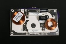
So far the results are kinda as predicted. Speaker volume with added resistors is notably different on my right, volume is lower. I wired in the Tweeter temporarily. I made up a crossover and soon will have a picture of it. I am anxious to install it in the left side to compare the OEM Xover, with my simple 1st order xover.
Attachments
I would be interested in seeing a sketch of the schematic of your simple 1st order crossover, as well as the picture you have promised.
Let's also have a picture of the "really well made" cabinets that you say make this venture worthwhile. 😎
Let's also have a picture of the "really well made" cabinets that you say make this venture worthwhile. 😎
You cannot see the picture in post #33?? https://audiokarma.org/forums/index...-crossover-advice.968615/page-2#post-14996908I would be interested in seeing a sketch of the schematic of your simple 1st order crossover, as well as the picture you have promised.
Let's also have a picture of the "really well made" cabinets that you say make this venture worthwhile. 😎
Last edited:
Looking at that picture there are two coils. They are different sizes so this must be one channel. The two resistors seem to be standard values for an L-pad for a tweeter. The two most likely possibilities are either a coil on the woofer and C-L-C for the tweeter... or L-C and C-L.
I would try a cross over simulator
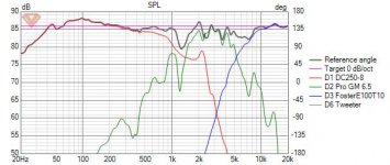
The Dayton has a significant peak in upper response
Not a super big deal, but likely 2nd order is needed.
I found the data sheet for the 6.5 inch mid and have a trace FRD response
its a good solid 93 to 95 dB driver.
So will be a fun one
Its my friday night so im playing around with a crossover design
I will post the FRD and ZMA files for the drivers in another post
Be nice to know the volume of mid chamber
since the enclosure will raise impedance
or Im guessing the original had a sealed back mid, so you need to add a mid chamber
wanted to have a accurate impedance curve to work with
the mid datasheet has no inductance value so I cant really
generate a accurate impedance curve. just have to work with the trace response I guess...
Last edited:
- Home
- Loudspeakers
- Multi-Way
- Driver Sensitivity