Hi Guys,
i have been trying to understand and be able to model the impedance of a driver for a while now and I am getting close but its just not working. Its really bugging me so I was hoping if I go through it step by step someone might be able to show me what I'm doing wrong.
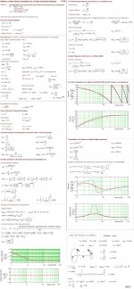
So, in one of MJK's papers he models the impedance of a 'Generic Driver' so i thought that would be a good benchmark, using the same parameters. (Page 24 of here, extract is shown below.)
So the parameters that he gives are as follows. (Some need converting to SI units).
Qms = 6
Qes = 0.429
Re = 8
Bl = 12.388
Sd = 200cm² which is 0.02m²
Cms = 3.872 x 10^(-4)
Mms = 26.168g which is 0.026168kg
I am going work out the Acoustic Impedance and MJK gives the Acoustic Equivalent Circuit for a driver as in the picture below:
Therefore, we need to convert Mms and Cms into Mas and Cas.
Cas = Cms * Sd² = 1.55 x 10^(-7)
Mas = Mms / Sd² = 65.42
We then need Rat, which MJK gives as:
Rat = Ras + [BL² / (Sd² * (Rg + Re))] (i am ignoring voice coil inductance for convenience).
Ras is given by MJK as (Bl² / Sd²) * [Qed / ((Rg + Re) * Qmd)]
I am going to set Rg (the source resistance) to zero as it is negligible.
So,
Ras = 3428.9
Rat = 3428.9 + 47957 = 51385.9
To find the impedance of the driver we just need to add the impedances of the resistive element (Rat) the Inductive element (Mas) and the Capacitive element (Cas).
The resistive element, being resistive, is the real part of the impedance so:
Za(real) = Rat
Inductance is purely imaginary reactive impedance and is jwMas.
Capacitance is purely reactive and is out of phase to Inductance so it is - (1 / jwCas)
Therefore:
Za(imaginary) = wMad - (1 / wCas)
I'll work out the Acoustic Impedance at 50Hz, as this is where the peak is on MJKs impedance graph.
Za(Real) = 51385.9
Za(Imag) = 2*PI*50*65.42 - (1 / 2*PI*50*1.55*10^(-7)) = 16.18
|Za| = SQRT(51385.9² + 16.18²) = 51385.9
To convert this into an electrical impedance (MJK's graph is electrical):
Ze = Bl² / [Sd² * Za]
Ze = 12.388² / (0.02² * 51385.9) = 7.466
MJK's impedance graph shows about 120ohms as 50Hz so it is way off. Also if I plot the graph it is such a steady rise and fall and looks nothing like a typical impedance curve. Interestingly though, if I set Rat = Ras then it is almost right....
Any ideas??
i have been trying to understand and be able to model the impedance of a driver for a while now and I am getting close but its just not working. Its really bugging me so I was hoping if I go through it step by step someone might be able to show me what I'm doing wrong.
So, in one of MJK's papers he models the impedance of a 'Generic Driver' so i thought that would be a good benchmark, using the same parameters. (Page 24 of here, extract is shown below.)
So the parameters that he gives are as follows. (Some need converting to SI units).
Qms = 6
Qes = 0.429
Re = 8
Bl = 12.388
Sd = 200cm² which is 0.02m²
Cms = 3.872 x 10^(-4)
Mms = 26.168g which is 0.026168kg
I am going work out the Acoustic Impedance and MJK gives the Acoustic Equivalent Circuit for a driver as in the picture below:
Therefore, we need to convert Mms and Cms into Mas and Cas.
Cas = Cms * Sd² = 1.55 x 10^(-7)
Mas = Mms / Sd² = 65.42
We then need Rat, which MJK gives as:
Rat = Ras + [BL² / (Sd² * (Rg + Re))] (i am ignoring voice coil inductance for convenience).
Ras is given by MJK as (Bl² / Sd²) * [Qed / ((Rg + Re) * Qmd)]
I am going to set Rg (the source resistance) to zero as it is negligible.
So,
Ras = 3428.9
Rat = 3428.9 + 47957 = 51385.9
To find the impedance of the driver we just need to add the impedances of the resistive element (Rat) the Inductive element (Mas) and the Capacitive element (Cas).
The resistive element, being resistive, is the real part of the impedance so:
Za(real) = Rat
Inductance is purely imaginary reactive impedance and is jwMas.
Capacitance is purely reactive and is out of phase to Inductance so it is - (1 / jwCas)
Therefore:
Za(imaginary) = wMad - (1 / wCas)
I'll work out the Acoustic Impedance at 50Hz, as this is where the peak is on MJKs impedance graph.
Za(Real) = 51385.9
Za(Imag) = 2*PI*50*65.42 - (1 / 2*PI*50*1.55*10^(-7)) = 16.18
|Za| = SQRT(51385.9² + 16.18²) = 51385.9
To convert this into an electrical impedance (MJK's graph is electrical):
Ze = Bl² / [Sd² * Za]
Ze = 12.388² / (0.02² * 51385.9) = 7.466
MJK's impedance graph shows about 120ohms as 50Hz so it is way off. Also if I plot the graph it is such a steady rise and fall and looks nothing like a typical impedance curve. Interestingly though, if I set Rat = Ras then it is almost right....
Any ideas??
An externally hosted image should be here but it was not working when we last tested it.
An externally hosted image should be here but it was not working when we last tested it.
An externally hosted image should be here but it was not working when we last tested it.
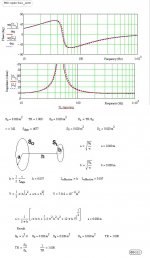
Ok, I just re-done this but by using the Electrical Equivalent Circuit and going straight for the Electrical Impedance and it seems to have worked. Still have no idea why the Acoustic Equivalent model doesnt work though.
So now I have the impedance curve of the box and the impedance curve of the driver I can work out the impedance curve of the system.
Can anyone point towards where I can work out the cone velocity (or volume velocity) from the impedance and a voltage source, eg (or pressure source, pg)?
So now I have the impedance curve of the box and the impedance curve of the driver I can work out the impedance curve of the system.
Can anyone point towards where I can work out the cone velocity (or volume velocity) from the impedance and a voltage source, eg (or pressure source, pg)?
..Can anyone point towards where I can work out the cone velocity (or volume velocity) from the impedance and a voltage source, eg (or pressure source, pg)?
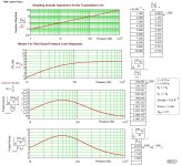
Hi,
I'm not sure if you are helped with with the information in these pictures....:
b🙂
Attachments
bjorno, I think those images may be old as the formulas are differet to the ones MJK has on his documentation. If they are do you have any more 'up to date' ones??
Hello,
If you read French I recommand to you the reading of my friend Francis Brooke's document :
http://francis.audio2.pagesperso-orange.fr/Modelisation_impedance_HP.pdf
(But even if you don't read French, the figures are very intersting by themselves).
Specially, please, notice the method developed by Robert X. to modelise the selfic rise impedance of the loudpeaker at HF. IMHO that method is superior to the others (Vanderkooy, Leach, Wright, Klippel, Kelvin, Thorborg...) and I use it myself.
Best regards from Paris, France
Jean-Michel Le Cléac'h
Last edited:
- Status
- Not open for further replies.