Altho this topology does appear to be positive feedback & increases stage gain slightly it does not qualify as feedback in the usual sense. Feedback over a single stage needs to go back to a cathode or grid where some gain can be realized. Back to the plate there is no gain possible.
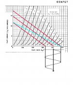
The driver tube used in this example is a 6SN7GT, a very common hookup. The load resister is 27K powered by 400 Volts B+. So the center red line is a 27K loadline terminated on the 400 volt point on the 6SN7GT plate family of curves.
The bootstrap connexion inserts some signal into the power supply B+ in the same phase as the main signal. That results in a higher impedance loadline & more gain occurs. But the increase in gain is small, the driver is usually a triode.
The other red lines are the same slope as the 27K loadline but they terminate at the limits set by the boot strap signal. A new loadline shewn in green is the result. This loadline looks like ~42K, (500 / 11.8)K. Calculating gain for the 27K loadline & assuming rp to be 7.7K & mu of 20 the gain is 15.56. With the 42K loadline the gain becomes 16.90.
The difference is 20 log (16.90/15.56) db or 0.72 db. Not much at all! I measured the difference of gain with & without bootstrapping on my version of Norman Crowhurst's Twin Coupled Amplifier. It was ~1,5 db.
The real benefit of bootstrapping is the longer loadline available to drive the following stage. Taking the extremes of the possible signal excursions from the control grid at zero volts at one end & -20 volts at the other looks like the 27K loadline would be OK at 280 volts peak to peak. For the bootstrapped 42K loadine the same measurement looks like 318 volts peak to peak.
In a practical circuit the boot strap signal would be much larger than in this example. But the 6SN7 curves don't go to a high enough voltage to shew that here.
Attachments
I recall some discussion about using over unity positive load Fdbk here:
https://www.diyaudio.com/forums/tubes-valves/211254-magnificent-television-tubes-17.html#post3763295
Someone on DIYAudio once posted a positive Fdbk triode tube load for linearizing purposes, by making the load line not just trend toward horizontal, but actually rising with higher plate voltage. Effectively making for a Negative Resistance load on the tube. The triode curves then had more equal spacing (overcoming the usual "roll-over" of triode curves).
That overdrive of the driver tube plates should be possible using a separate specially wound autotransformer driving taps on its primary by the power tubes, the ends of the winding's driving the preceding plate resisters.🙂
Would it help, don't know but looks interesting.😀
Would it help, don't know but looks interesting.😀
I found these on over-unity positive Fdbk for 3rd harmonic cancellation in P-P:
https://www.diyaudio.com/forums/tubes-valves/294308-power-triode-expensive-6.html#post4780852
https://www.diyaudio.com/forums/tubes-valves/289449-advice-budget-valve-amplifier-3.html#post4672554
https://www.diyaudio.com/forums/tubes-valves/289449-advice-budget-valve-amplifier-4.html#post4674103
https://www.diyaudio.com/forums/tubes-valves/289449-advice-budget-valve-amplifier-5.html#post4674852
That is an interesting amp, I wonder if anyone did a build. When I did the build & article on the driver for low mu triodes back about 20 yrs ago I thought too much positive FB to the driver plates might be unstable & noted that. But I went no further than the 40% UL taps on the OPTs I had. That worked well, I had to move on. The real work that brought $$$ home had priority.🙂