Since I don't know yet whether and which problems may be associated with the bootstrapping buffered from the emitters, I'm a bit hesitant to have this as the only option. By adding two Zener diodes as options (D7 and D8 in the schematic attached), I could "downgrade" to bootstrapping from the tail node. Two CCS and two Zeners basically in parallel are kind of redundant, but I have them on the PCB anyway.

Since the CCS show good matching, I could also connect the Zener anodes to the emitter, thus having bootstrapping from the emitters without buffers.

What do you think?
Would using two CCS and two Zeners fed to each emitter be a good or bad idea? The benefit would be bootstrapping from the emitters without buffers.
Since the CCS show good matching, I could also connect the Zener anodes to the emitter, thus having bootstrapping from the emitters without buffers.
What do you think?
Would using two CCS and two Zeners fed to each emitter be a good or bad idea? The benefit would be bootstrapping from the emitters without buffers.
Sorry for the messy schematics I posted.
I wonder how the magic floating voltage (battery) of the boostrapped cascode shown in textbooks could be generated in reality.
Wouldn't a CCS and Zener be the most obvious solution?

I wonder how the magic floating voltage (battery) of the boostrapped cascode shown in textbooks could be generated in reality.
Wouldn't a CCS and Zener be the most obvious solution?

Elegant solution since this is self biasing. The gate of the JFET could also be tied to the emitter.
Vds of JFETs is rather limited so the usefulness of the JFET cascode is limited to low voltage applications.
I just have Kolinummi's book open on page 127.
The circuit with the battery cancels the cascode transistors base current, but this works only with the battery generating the offset. The cancellation effect is gone using a buffer. And the problem is nonexistent with a JFET.
I found some photos I saved from the internet to my phone.
Unfortunately without context.
Seems like the idea with the Zeners and CCS is not too far off.
Both examples have capacitors in parallel either to the Zeners or resistors generating the offset. Looks like the capacitors are important.
Unfortunately without context.
Seems like the idea with the Zeners and CCS is not too far off.
Both examples have capacitors in parallel either to the Zeners or resistors generating the offset. Looks like the capacitors are important.
Attachments
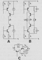
Those are from Hawksford's paper on the bootstrap cascode technique if I'm not mistaken.
Edit: Yes, see here
Edit: Yes, see here
Last edited:
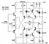
Hi LK, may I know what is your rationale adding resistors R15, R16 in your circuit?
I had a closer look at the mechanism of the emitter resistors added to the cascodes. What they do is spoiling the positive feedback of the cascode arrangement, but this also means that they may spoil the performance if the value is too high. A value of 100R seems far too high. Maybe 10R is enough to avoid instability without ruining the performance. I read that those resistors are good from multiple sources, like here Nelson Pass: https://www.diyaudio.com/community/threads/cascodes-the-truth-is-out-there.63187/post-7047078.I heard that those resistors may help with stability of the cascodes. Not sure.
Since I added base stoppers to the cascodes, R15 and R16 may be superfluous.
I illustrated the effect of the cascode emitter resistors stepped 1R, 10R and 100R:
@Lee Knatta
Yes, 100 Ohm is quite large and mitigates the benefit of having cascodes, I am glad you found out the negative consequence of these resistors when being too large, but I understood also your general notion of using additional resistors for damping purpose.
Another thing while typing here, you mentioned the bootstrapping of the cascode using a battery in post #42, I don't know what Kolinummi have written in his book, but I think the battery symbol is some times in theoretical discourse used to just symbolize a needed fixed potential between two nodes without going into what the practical circuit would look like.
And a practical circuit could be as shown in your post by using something based around a zener diode, a capacitor in parallel would be a good addition as zeners have a bit high impedance and are somewhat noisy too.
Yes, the battery symbol is used exactly for that: Kolinummi's schematics use the battery symbol all the time to indicate there needs to be a voltage offset. It is up to the reader to figure out how to practically implement this voltage offset then. The book is excellent BTW, but some ideas may be difficult to implement in reality because often he does not explain what kind of hacks one might need to add in order to get something really stable in reality.
Apart from shunting noise, which is only effective if the impedance of the reference (Zener, LED, resistor) is high, I believe the parallel capacitor is aiding stability since the reference would be bypassed at high frequency reducing positive feedback.
Apart from shunting noise, which is only effective if the impedance of the reference (Zener, LED, resistor) is high, I believe the parallel capacitor is aiding stability since the reference would be bypassed at high frequency reducing positive feedback.
Thank you LeeHere is a short follow-up:
I promised to write about any difference in performance of the two bootstrapping schemes I built.
However I blew up the front end module with the emitter buffered bootstrapping scheme so there are no results yet.
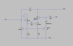
But I can report about practical CCS variation.
The schematic of my CCS is attached (you asked for the schematic earlier).
I measured 225mV across each 100R sense resistor (test points CP1 to CP2 and CN1 to CN2 in the schematic I posted previously).
While the current is slightly off compared to simulation (closer to 2mA), the two CCS show good matching with random parts from the same batch. So as long as the two CCS stay at the same temperature, the current output is very similar.
I wonder if bootstrapping concept can be applied to cascoded VAS and if it is of any benefit. Comparing to Hawskford enhanced cascode?I quickly did a simulation to figure out how much better the individual bootstrap from the emitter is than the scheme I used previously, which is just three LEDs in series between the tail node and the common bases of the cascodes.
Here is the situation with the differential cascodes:
View attachment 1084818
That would be with bootstrapping from the tail:
View attachment 1084819
All at 100kHz to exaggerate the effect. While my amplifier uses TPC, NFB is not very effective at such high frequency. Probably with plain Miller compensation, the effect would be more obvious.
Michael's scheme works better, but is it worth it? The more simple bootstrapping from the tail node works well, too.
Then I set up a voltage controlled voltage source with 4V voltage source on top to drive the cascodes from the VAS output:
View attachment 1084820
Obviously the phase shift makes the non-inverting transistors Vce more variable.
The same driven from the amplifier output:
View attachment 1084821
Not that much worse.
Just for fun I configured the cascodes reference to ground instead of any bootstrap:
View attachment 1084822
Ouch, this is really bad!
I would conclude that bootstrapping is good overall, regardless if from the tail, the emitters, VAS or amplifier output. There are slightly better ways to do it and slightly worse.
I should have done such simulation much earlier.
- Home
- Amplifiers
- Solid State
- Driven Cascode Novelty Circuit