I also use carbide drills and a drill press. without a press, I was able to break around 10 bits and not even finishing one board. 
I also second what they said about HSS bits last quite a while with phenolic boards and wear down very quickly with FR4 boards.
what about cutting the PCB's to size, what do you guys use?
for FR2, I use the score and snap method. for FR4, I have a cutting disc and run the entire lenght until it goes through.
I would love to have a guillotine but not available anywhere here.
I only use FR4 cos I'm posh
I cut the board oversize about 5mm all round with a hacksaw, filing the edges over.
Then after etching, drilling and tinning I trim again with a hacksaw. I finish off finely with a hand held belt sander.
I too would dearly love a guiilotine. £300 though.
I cut the board oversize about 5mm all round with a hacksaw, filing the edges over.
Then after etching, drilling and tinning I trim again with a hacksaw. I finish off finely with a hand held belt sander.
I too would dearly love a guiilotine. £300 though.
Actually, it does matter.
If you drill first, you always run the risk of excessive undercut of the copper at the hole site... making your holes end up with no copper near them. Not the ideal conductivity solution.
You could take extra steps to prevent it... but with DIY boards, it is much easier to use the etched hole as a guide for a drill bit.
impsick said:i see, i was wondering if it wouldnt be easier to drill 1st and then go back and maybe fat'n those edges around the whole with a sharpie? ( just so you dont have that problem of drilling out the copper)
If you drill first, so the copper round the hole gets eaten away too much, then the last thing you want to do is risk taking off more copper. And would you really be bored enough to drill a board then go round every hole again with another tool?
Drilling after etch also has the advantage that the drill centres itself in the slight indent of the hole.
jpg said:I bought used carbide drill bits on ebay from a PCB manufacturer for next to nothing (compared to what they'd cost new). They came in perfect shape.
Both Rapid Electronics and ESR sell re-ground (ex CNC) bits in the UK, £1.90 each compared to £2.88 new for 1mm.
Rapid cheaper but min. order 10-pack in the re-ground.
richie00boy said:
If you drill first, so the copper round the hole gets eaten away too much, then the last thing you want to do is risk taking off more copper. And would you really be bored enough to drill a board then go round every hole again with another tool?
Drilling after etch also has the advantage that the drill centres itself in the slight indent of the hole.
I find the self-centering factor more significant if trying to drill by hand, when using a drill press and carbide bits it can be as likely to break a bit if the press table isn't really slippery so the board moves easily, otherwise having the bit slightly off-center and an indented hole moves the bit which a carbide bit will not like doing, breaking if very small, or it just ignores the indentation and drills where it starts if it's off of the indentation enough.
So far as when to drill, it might depend- on where the weakest link is in the whole fabrication process. If you drill first, it is not a big deal to take an industrial sharpie marker and touch each hole to cover the exposed copper. As for "bored enough", you're being too subjective, it's a minor bit of time and are you really "bored enough" to build an amp? In the grand scheme of things, one does what they need to, taking their time to do_it_right or they miss the point of DIY.
That doesn't make drilling first better per se, but if someone didn't have their fab process down good yet and was left with marginally adequate copper left behind around holes, one way or the other they will have to either make the adjustments to their current board or spend a lot more time remaking all their boards till they get their process refined enough to get it right the first time.
It's a great point of pride to have a "pretty" etched board, but honestly it doesn't matter that much, even if holes were etched away some that's not a big deal, it could actually sound BETTER that way if you used silver solder to bridge where the copper would've been still if we're trying to contrast what the effects of the copper would've been sonically instead of the (more typically assumed tin/lead) solder bridging the remaining gap. That's taking a point and stretching it beyond reason though, with the whole board done with copper, the mechanical aspects and ease of soldering are better with the copper still right up to the hole.
On an unrelated note, the choice of HSS or carbide is pretty simple. Carbide is better if the drill can be held by a rigid mechanical means so an excessive number of bits aren't broken. Excessive tends to mean the cost of broken bits is higher than cost to replace the HSS bits from wearing out faster than carbide. I don't find carbide to cut any better than HSS, if you find it makes better holes I suspect it's only because the (HSS) bit was dull already and needed replaced (or sharpened but that's hard to DIY on such tiny bits).
Some of the guys here who aren't engaged in industrial/metalworking stuff are sometimes fascinated by industrial products.
I sell collets for clamping small drills. The collet diameters go down to 0.010" (.25mm) and the concentricity is 0.000080" (.002 mm) at 4d (that's four times the diameter of the tool) when mounted in the tool holder. We sell these ranges of collets up through ~3/8". Collets range from $85-105. Tool holders are rated from 25,000-40,000 RPM with a balance of 2 gram/mm. Holders are about $375.00. So figure a nice round $500 to drill a hole. That tool might be mounted in a spindle that costs $40,000 (2000 hrs. between $10,000 rebuilds) on a machine that sells for $500,000. At those prices, there's a good chance that the hole will wind up pretty much where you told the machine to put it.
Just thought you would like to know.
I agree with the previous post. HSS is great for a lot of stuff and you don't need to feel bad when you break them. Carbide requires more rigid setups.
impsick said:i was wondering what size drill bits you guys are using when drilling out your pcbs at home? i have only found 1/16 inch bits and thats too big! where do you guys get your smaller bit size?
I typically drill batches of boards, with something like 6500 holes per batch, which usually means about one hole every two seconds or so, for about half a day. Typically, about 2/3 of the holes I drill are in .031" double-sided FR4 1 oz copper laminate, with most of the remainder in .062" double-sided FR4 1 oz copper laminate, and a small fraction in .062" single-sided.
I usually get my drill bits from http://www.ebay.com . If you wait for the right auction, I think it might cost about $25 for a box of 50 of .032" or .035" used/repointed carbide bits, with 1/8" shanks (about a year ago, anyway).
I run them in a 30,000 RPM Dremel or Dremel-like clone. My son "made" a drillpress/stand for the Dremel, for me, starting with a small and very bad/cheap beat-up old benchtop drillpress. He removed the old movable motor/head, replaced it with a handmade cradle/holder for the Dremel (big u-bolts, etc), added a shim or two to align everything, and totally removed the runout (wobble or "play" that's perpendicular to the rotation axis), by attaching two (more-or-less-)parallel springs between the movable and non-movable parts. The only runout, now, is in the Dremel itself (and some are better than others; Make sure that you read the manual about the initial "break-in" run.).
As far as I'm concerned, the carbide bits are the only way to go. I do break them, once in a while. But "that's the way it goes". They usually last for WELL over 1000 holes, on the average, before I manage to break them, which is often not just random, but because I did something accidentally, that I knew would break the bit.
I have also, occasionally, had to use a hand-held Dremel and .032" carbide bit to drill five or ten new holes in an already-populated prototype PCB that needed to be modifed, and have used the mounted Dremel and .032" bit to carefully "router"-away small parts of traces, e.g. to "open" a prototype's trace where I needed to insert a series component, and have not broken any bits, while doing either of those.
I used to use the "wire-gauge type" HSS (high-speed steel) bits; #60 or something like that. I used them in a "standard" (i.e. non-Dremel-type/non-high-speed) "floor-standing" drillpress, with a miniature chuck to hold them in the larger chuck. They always quickly got too dull to use; certainly within about 300 holes, even with lubrication while drilling. I went through a LOT of HSS bits, back when I was doing it that way. I would never want to use HSS bits for PCBs, again, except for drilling the relatively-few 1/8" mounting holes. (But note that I have never trid the HSS bits with a 30,000 RPM tool.)
For me, the HSS bits also tended to pull the edges of the holes up out of the plane of the rest of the copper, especially when they were starting to get dull, which was almost immediately. The carbide bits, on the other hand, go through the PCB like it's almost not there, and always make very clean holes. And I have never noticed any change in sharpness, of a carbide bit, before I broke it, even if it lasted for several thousand holes.
Tom Gootee
http://www.fullnet.com/~tomg/index.html
-
impsick said:i was wondering what size drill bits you guys are using when drilling out your pcbs at home? i have only found 1/16 inch bits and thats too big! where do you guys get your smaller bit size?
To better-answer your original question, in case you want to drill some holes "today": I used to get the wire-gauge HSS drill bits at our local True Value hardware store.
- Tom Gootee
http://www.fullnet.com/~tomg/index.html
-
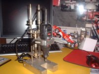
Home made PCB drill
I made a simple PCB drill by directly connecting a .8mm drill bit to the shaft of a 12v dc motor that i hacked out of an old car sterio.I used the plastic part of a hyper dermic needle and super glue to couple the bit to the shaft.. Trust me it makes a great fast drill.Just remember to by pass the small speed control board that are in built into these motors.
I made a simple PCB drill by directly connecting a .8mm drill bit to the shaft of a 12v dc motor that i hacked out of an old car sterio.I used the plastic part of a hyper dermic needle and super glue to couple the bit to the shaft..
Trust me it makes a great fast drill.Just remember to by pass the small speed control board that are in built into these motors.The drillng of a PCB can be done by a normal electric hand drill machine using HSS drill bit. It should be light enough to be held on your thigh.
Punch the PCB holes lightly, like in metal working, by judging the laminate requirement. Hold the PCB in your left hand. Hold the drill on one of your thighs and position it on drill Zero point, and drill.
U need a little bit of experience for this.
Beware: Keep fingers away from the drill bit that is coming out on the other side of the laminate.
Gajanan Phadte
impsick said:gootee, really i went to lows hardware originally but only found 1/16 inch. i'll try some other places thanks
There almost "has to" be a local hardware store that carries the "wire gauge" bits, there, if there was one in the small town in which I live.
The #60 bit, IIRC, was 0.04" (1/25"). And they had smaller ones, too, I think.
I don't remember if you said what kind of drill machine was to be used. But if you have only a standard type of drill, note that even with my drillpress's chuck closed tightly, the tiny #60 bit was not clamped in at all, and could slide in and out without even touching the sides. I initially tried using it with something wrapped around the top of the bit (tape, or aluminum foil), to make it fat-enough to be able to be clamped by the chuck. It sort-of worked. But there were problems with alignment that caused wobbling. It was still usable, but not optimal. And, of course, they got dull so quickly that it would be a pain to have to wrap each one. I bought a very small chuck, from the same hardware store, that would hold the bits AND fit into my standard chuck. That worked, but I still always had problems with alignment that usually caused some (or even quite a bit of) wobble at the tip of the bit. It still works more-or-less usably, though, especially if you have etched small holes in the copper on the PCB, where each hole will go, which usually should "catch" the tip of the bit and stop the wobble, just as the bit contacts the board. I remember that sometimes the tip of the bit seemed to be wobbling in a 1/8"-diameter circle. But the etched hole still almost always captured it and drilling was "OK". That sort of stuff should be usable for drilling just a few boards, with a few hundred holes, every once in a while. But, as I have already said: in my opinion, you'd be better-off finding some carbide bits and using a Dremel-type rotary tool (the fastest one you can find). Even Wal-Mart has the rotary tools, and possibly some small bits for them, and, at times at least, they have had the drill-stands for them.
You could even make your own DIY drillstand/drillpress. ALL you REALLY _need_ is something that a) restricts the motion to being (almost) only vertical, and b) probably something that holds-up the weight of the tool. A "long-enough" piece of wood (or of almost anything), with a holder at the end for the tool, and a "hinge" at (or some flex versus) the other end, should work.
The vertical motion of the tool only needs to be 1/4" or so. If the supporting member is long-enough, the motion at the tool end, even though it's technically a circular arc, will be linear-enough for drilling a PCB without breaking a carbide bit. So, even a long-ish hanging spring, holding the tool up, with a couple of slightly-flexible (or hinged) rods or dowels or aluminum "L-beams", or whatever, at an angle to each other as they leave the tool so they prevent side-to-side motion, might work (or, as mentioned, a long-enough piece of, say, 1"x4" wood, or a flat metal bar).
For cylindrical "V"-frame members, each "hinge" could be as simple as a flexible "boot", made of something like a very short piece of rubber or plastic tubing, with a screw or bolt through one end of it, fastened into something, with the cylindrical rod or dowel jammed or glued into the other end. At the tool end, the connection could be as simple as a "pipe clamp" (the screw-tightenable metal circular strap type), which could clamp, to the rotary tool, whatever you need to use to connect the rods or dowels or L-beams or wood plank to the tool. If, for example, you used metal threaded rods to make the "V" (available at the same hardware store as the bits, no doubt), then you could probably put a compatibly-threaded machine screw THROUGH the clamp's strap (head against tool), optionally add a nut to clamp it against the strap, and then use a "coupling nut" (an elongated nut) to attach the rod. (Note that you might need TWO such V-frames, attached at different heights on the rotary tool, to help keep the tool more-reliably vertically oriented. While you're at it, you could add a handle or protrusion of some sort, to make it easier to hold and move the tool up and down.)
There are also Flex-Shaft drives available for Dremel-type rotary tools (some on ebay, usually, too), so that the tool can be a few feet away and all you need to hold (or mount on a drillpress) is a small, light "handpiece", not much larger than a Sharpie marker. I have one of those flex-shafts, too, but have never tried using it to drill PCBs, either handheld or mounted on a drillpress-like stand. (I was/am planning to use the flex-shaft drive on the z-axis of a computer-controlled (CNC) PCB-drilling machine that I was building (mostly out of old/free dot-matrix and daisy-wheel printer parts), if I ever get time to get back to finishing it.)
Sorry to have blathered-on for so long, about all of that! Mechanical design is "way out of my area". So there are probably much-better ways to make a simple DIY drill-alignment mechanism. You might also want to think about keeping the tool stationary and moving the board-holder, instead.
Good luck.
- Tom Gootee
http://www.fullnet.com/~tomg/index.html
-
GOOTEE YOU CAN TYPE!!! thanks for the info.
hey if anyone reads this im going nuts over here on Eagle Cadsoft!!!! ok so i have these components going to ground right... so i use the polygon to make that copper ground plane but it wont connect to any components when i rattsnest. how do i make them connect? thanks whoever.
hey if anyone reads this im going nuts over here on Eagle Cadsoft!!!! ok so i have these components going to ground right... so i use the polygon to make that copper ground plane but it wont connect to any components when i rattsnest. how do i make them connect? thanks whoever.
- Status
- This old topic is closed. If you want to reopen this topic, contact a moderator using the "Report Post" button.
- Home
- Amplifiers
- Chip Amps
- drilling pcbs