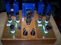
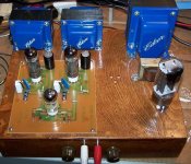
Nice PP Bruce! Got some more pictures? Kinda hard to tell what you've created here...seems your amp is butted up against another unit I see.
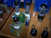
Curious & kinda dangerous with the exposed PC board....here's hoping no one near is taken to touching anything there.......ZZaapppp! Perhaps your not done quite yet?
____________________________________________________Rick...........
Curious & kinda dangerous with the exposed PC board....here's hoping no one near is taken to touching anything there.......ZZaapppp! Perhaps your not done quite yet?
____________________________________________________Rick...........
Last edited:
Thanks Richard,
All safety issues are very well addressed.
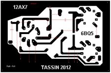
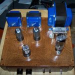
Your correct, I have a 6V6 SE on one side of the PP and on the other side is a 6BQ5 SE. All pc board are my own creation as are the chassis.
Bruce
All safety issues are very well addressed.
Your correct, I have a 6V6 SE on one side of the PP and on the other side is a 6BQ5 SE. All pc board are my own creation as are the chassis.
Bruce
Attachments
Looks nice.
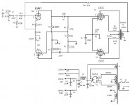
You might want to change R8 and R9 from 1/2W to 1W as the working voltage rating of the 1/2 W resistors are typically 250V. 1W resistors generally have a rating of 350V or greater.
You might want to change R8 and R9 from 1/2W to 1W as the working voltage rating of the 1/2 W resistors are typically 250V. 1W resistors generally have a rating of 350V or greater.
Thanks Gimp, I'll look into it. This is a clone of a Pilot 505 amp. I used the values shown on the schematic. I'm not an EE, just a cludger.
R11 seems a little to big and can be rolling off the highest frequencies of the audio spectrum, as a quick experiment you could put in parallel with it another resistor of say 15k with alligator clips and listen carefully to see if you can hear an improvement in the sound. Try listening to the hi-hat and cymbals in a suitable song to make the difference audible (if any).
Also you can try playing with the values of R5 and R6 to fine tune the phase inverter, you can momentarily wire a 500k pot and play around until you find the sound you like, then measure the resistance of each branch and replace the pot with the closest value resistors you can find (In fact leaving the pot isn´t so bad of an idea IMHO because if you replace the 12ax7 you can readjust easily the phase inverter)
Other than that it is a neat build, enjoy it.
Nice work Bruce. I see where you are going with. I will toss this around
once again very nice job!!
Build safe and Listen back.
once again very nice job!!
Build safe and Listen back.
Hello to all @ DIY
To the e-mail I was asked a question now this this post was from Bruce Heran on the poddwatt.
Power and audio output transformers for the "PoddWatt: 5751 SRPP / EL84 (6BQ5) Push-Pull (class-A) Tube Amp" by Bruce Heran of Oddwatt Audio.
To the e-mail I was asked a question now this this post was from Bruce Heran on the poddwatt.
Power and audio output transformers for the "PoddWatt: 5751 SRPP / EL84 (6BQ5) Push-Pull (class-A) Tube Amp" by Bruce Heran of Oddwatt Audio.
- Home
- Amplifiers
- Tubes / Valves
- drdwers