or How I Learned To Stop Worrying And Love The Bits *
It was about two years ago, when I first read about the CD-PRO2 unit. Later, I read in a number of forums and sites about the superiority of the TDA1541 dac chip in an non-oversampling mode. Since the TDA1541 accepts an I2S bus and the CD-PRO provides an I2S bus, I thought that connecting these two via the I2S bus should be superior to the common used S/PDIF connection, thus eliminating the double digital encoding/decoding. So, I decided to purchase the CD-PRO2 unit and build a TDA1541 DAC.
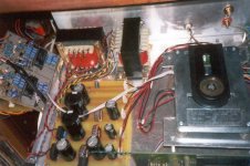
First, I comleted the CD-PRO2 cd player and I was quite satisfied from the outcome. Although from its internal DAC, the sound I got was way better from my previous Marantz CD-52.
After that, it was time to build the DAC. I had already searched in the Internet and had found a number of implementations. What I finally decided was two paralleled non-oversampling TDA1541s, TL431 shunt regulators on each chip, passive I/V conversion and tubed output buffer with a 6C45Pi.
The DAC worked perfectly from the first moment I fired it up. From the first notes I could hear a great difference between the built-in and the external DAC (I connected the TDA1541 DAC to a free input of my preamp, so I could have an instant comparison between the two). The sound turned out to be more “analog”. There was much air around instruments, while the soundstage was wider and deeper.
Just out of curiosity and due to its simplicity, I breadboarded a TDA1543 DAC to compare it to the 1541. Although not built to the SOTA standards, I must say that there is no comparison between the two.
Then, I decided to try something diferent. Instead of a resistor load, I wanted to try a CCS load on the output buffer tubes. It seemed that Gary Pimm’ s BBMCCCS should do the job. After completing and testing the two CCSs, I connected them to the circuit and fed with music. God, this was a HUGE improvement! Suddenly the soundstage aquired a great width and depth, resolution was superb, macro- and micro-dynamics were great, analysis was really high, sound is sweet and physical lacking all the harshness I was used to hear from digital, in all, I can say it was an unbelievable sound. I had never heard digital sound beeing so analog. One more thing I noticed is that, although many say that a NOS DAC lacks highs due to the sinx/x effect, I must say that highs are much better than those from the internal DAC.
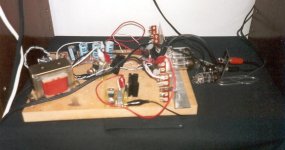
Although the tube circuit is still in a breadboard form, HT power supply is the simplest I could make just to check the circuit, I’ m so satisfied from the sound, that I can’ t take the decision to take the whole thing apart and build it properly, I just want to listen to music.
Next, I will have to build a proper HT power supply, separate the parts in two cases (one for the transformers – quite a lot of them – and raw power supplies and one for the CD-PRO2 unit, power supply rgulators, DAC board and output buffer) and take care of the esthetics of the cases.
In conclusion, I must say: thank you Alessandro, Thorsten, Lesha, Garry and everyone else who led me to the realisation of a great sounding digital source.
Evangelos
* Inspired from the title of Stanley Kubrik’ s film:
Dr Strangelove or How I Learned To Stop Worrying And Love The Bomb
It was about two years ago, when I first read about the CD-PRO2 unit. Later, I read in a number of forums and sites about the superiority of the TDA1541 dac chip in an non-oversampling mode. Since the TDA1541 accepts an I2S bus and the CD-PRO provides an I2S bus, I thought that connecting these two via the I2S bus should be superior to the common used S/PDIF connection, thus eliminating the double digital encoding/decoding. So, I decided to purchase the CD-PRO2 unit and build a TDA1541 DAC.
First, I comleted the CD-PRO2 cd player and I was quite satisfied from the outcome. Although from its internal DAC, the sound I got was way better from my previous Marantz CD-52.
After that, it was time to build the DAC. I had already searched in the Internet and had found a number of implementations. What I finally decided was two paralleled non-oversampling TDA1541s, TL431 shunt regulators on each chip, passive I/V conversion and tubed output buffer with a 6C45Pi.
The DAC worked perfectly from the first moment I fired it up. From the first notes I could hear a great difference between the built-in and the external DAC (I connected the TDA1541 DAC to a free input of my preamp, so I could have an instant comparison between the two). The sound turned out to be more “analog”. There was much air around instruments, while the soundstage was wider and deeper.
Just out of curiosity and due to its simplicity, I breadboarded a TDA1543 DAC to compare it to the 1541. Although not built to the SOTA standards, I must say that there is no comparison between the two.
Then, I decided to try something diferent. Instead of a resistor load, I wanted to try a CCS load on the output buffer tubes. It seemed that Gary Pimm’ s BBMCCCS should do the job. After completing and testing the two CCSs, I connected them to the circuit and fed with music. God, this was a HUGE improvement! Suddenly the soundstage aquired a great width and depth, resolution was superb, macro- and micro-dynamics were great, analysis was really high, sound is sweet and physical lacking all the harshness I was used to hear from digital, in all, I can say it was an unbelievable sound. I had never heard digital sound beeing so analog. One more thing I noticed is that, although many say that a NOS DAC lacks highs due to the sinx/x effect, I must say that highs are much better than those from the internal DAC.
Although the tube circuit is still in a breadboard form, HT power supply is the simplest I could make just to check the circuit, I’ m so satisfied from the sound, that I can’ t take the decision to take the whole thing apart and build it properly, I just want to listen to music.
Next, I will have to build a proper HT power supply, separate the parts in two cases (one for the transformers – quite a lot of them – and raw power supplies and one for the CD-PRO2 unit, power supply rgulators, DAC board and output buffer) and take care of the esthetics of the cases.
In conclusion, I must say: thank you Alessandro, Thorsten, Lesha, Garry and everyone else who led me to the realisation of a great sounding digital source.
Evangelos
* Inspired from the title of Stanley Kubrik’ s film:
Dr Strangelove or How I Learned To Stop Worrying And Love The Bomb
Well,
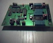
You got me very interested. I'm looking for a nice output for the pcb below! Is it possible to post some schematics or a link to them? Also the powersupply you used is interesting.
Possible improvements?:
- better xtal for cdpro (Elso or Guido)
- dem reclocking
- split i2s for dacs: one dac is left, one is right channel.
Thanxs,
Guido
Attachments
Guido,
The output stage I used is very simple: a single triode (6C45Pi) in common cathode configuration, with a constant current source as an anode load. You can see a basic schematic at Lesha' s site:
http://users.podolsk.ru/boga/DAC.html
You can also check A. Galavotti' s design:
http://www.geocities.com/agalavotti/zerodac.htm
Both these are almost identical and they use a choke as an anode load. Having read a lot about the merits of a CCS, I decided to use Garry Pimm' s BBMCCCS, as it is simple to build, costs almost nothing compared to an anode choke and it doesn' t need so much space in the cd player box such as an anode load choke.
I can' t figure out what power supply you are referred to.
Regarding your suggestions for further improvemnet, I have already considered the first two (better xtal and reclocking of the three digital lines), but the third one is out of question, as it requires digital techniques and designs that I don' t have and also a redisigning of the pcb.
Regards,
Evangelos
The output stage I used is very simple: a single triode (6C45Pi) in common cathode configuration, with a constant current source as an anode load. You can see a basic schematic at Lesha' s site:
http://users.podolsk.ru/boga/DAC.html
You can also check A. Galavotti' s design:
http://www.geocities.com/agalavotti/zerodac.htm
Both these are almost identical and they use a choke as an anode load. Having read a lot about the merits of a CCS, I decided to use Garry Pimm' s BBMCCCS, as it is simple to build, costs almost nothing compared to an anode choke and it doesn' t need so much space in the cd player box such as an anode load choke.
Also the powersupply you used is interesting.
I can' t figure out what power supply you are referred to.
Regarding your suggestions for further improvemnet, I have already considered the first two (better xtal and reclocking of the three digital lines), but the third one is out of question, as it requires digital techniques and designs that I don' t have and also a redisigning of the pcb.
Regards,
Evangelos
Evangelos,
This got me confused: "Then, I decided to try something diferent. Instead of a resistor load, I wanted to try a CCS load on the output buffer tubes." Did you mean choke instead of resistor?
Thought you were talking about the resistors on the DAC output. I'm not so much into tubes.. I'll checkout BBMMCCCS.
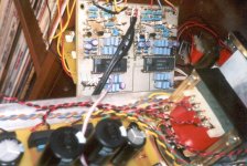
I was talking about DAC powersupply, are you using TL's? Think i see three of them per DAC. I was thinking of trying a different PS for the analog and digital (TL's) DAC supplies.
My 2 cents:
DEM reclocking is not the same as reclocking i2s! It is removing the one cap between pin 16 & 17. Doing this by heart, not sure if these are the right numbers! Think it is the brown cap in the pics, i used the same type btw.
It can be replaced by some logic feeding a clocksignal derived from i2s clock. Still have to look into this some day. Never saw the design on the net, but i think it came from a guy called Henk ten Pierick (sorry if i mis-spelled the name).
Changing the xtal and async reclocking i2s rule eachother more or less out! If you reclock i2s there is not much use anymore for an excellent xtal in the drive. Reclock async OR put a nice clock in the drive.
Option three, requires more work: Put the clock in the dac and reclock synchroniously, (check out tda1545 post or my design).
Splitting i2s requires some logic, do a search here and you will find the details to do this. It would require you to cut the i2s lines to one dac and feed both from some logic. Not a huge change.
GuidoB
(mind the B, it's not a T :-> )
This got me confused: "Then, I decided to try something diferent. Instead of a resistor load, I wanted to try a CCS load on the output buffer tubes." Did you mean choke instead of resistor?
Thought you were talking about the resistors on the DAC output. I'm not so much into tubes.. I'll checkout BBMMCCCS.
I was talking about DAC powersupply, are you using TL's? Think i see three of them per DAC. I was thinking of trying a different PS for the analog and digital (TL's) DAC supplies.
My 2 cents:
DEM reclocking is not the same as reclocking i2s! It is removing the one cap between pin 16 & 17. Doing this by heart, not sure if these are the right numbers! Think it is the brown cap in the pics, i used the same type btw.
It can be replaced by some logic feeding a clocksignal derived from i2s clock. Still have to look into this some day. Never saw the design on the net, but i think it came from a guy called Henk ten Pierick (sorry if i mis-spelled the name).
Changing the xtal and async reclocking i2s rule eachother more or less out! If you reclock i2s there is not much use anymore for an excellent xtal in the drive. Reclock async OR put a nice clock in the drive.
Option three, requires more work: Put the clock in the dac and reclock synchroniously, (check out tda1545 post or my design).
Splitting i2s requires some logic, do a search here and you will find the details to do this. It would require you to cut the i2s lines to one dac and feed both from some logic. Not a huge change.
GuidoB
(mind the B, it's not a T :-> )
Guido,
No, I was talking about loading the anode of the outpur buffer tube, where I used a constant current source. For the BBMCCCS check out here:
http://home.pacifier.com/~gpimm/
Yes, I use three TL431s on each dac chip, that means a total of six TLs. A lot of experienced enginneers support the idea of using different PS lines for each supply input. I even used different transformers for the digital (+/- 5 V) and analog (-15 V) supply lines, both with an ES shield.
Then I will stick on replacing the built in with a (higher quality, low jitter) external clock. Any suggestions? Kwak clock or Guido T's?
As for option 3 changes, I think I will stick to my current design as I' m not that much into bit and bytes.
Evangelos
No, I was talking about loading the anode of the outpur buffer tube, where I used a constant current source. For the BBMCCCS check out here:
http://home.pacifier.com/~gpimm/
I was talking about DAC powersupply, are you using TL's? Think i see three of them per DAC. I was thinking of trying a different PS for the analog and digital (TL's) DAC supplies.
Yes, I use three TL431s on each dac chip, that means a total of six TLs. A lot of experienced enginneers support the idea of using different PS lines for each supply input. I even used different transformers for the digital (+/- 5 V) and analog (-15 V) supply lines, both with an ES shield.
Changing the xtal and async reclocking i2s rule eachother more or less out! If you reclock i2s there is not much use anymore for an excellent xtal in the drive. Reclock async OR put a nice clock in the drive.
Then I will stick on replacing the built in with a (higher quality, low jitter) external clock. Any suggestions? Kwak clock or Guido T's?
As for option 3 changes, I think I will stick to my current design as I' m not that much into bit and bytes.
Evangelos
Hi,
I only have experiece with GuidoT clocks. Can't comment on differences. Check out the Vcc of the chip where the clock is connected to. Might be 3.3 volts. Check some other post around here for that!
Guido
I only have experiece with GuidoT clocks. Can't comment on differences. Check out the Vcc of the chip where the clock is connected to. Might be 3.3 volts. Check some other post around here for that!
Guido
- Status
- Not open for further replies.
- Home
- Source & Line
- Digital Source
- Dr Digital