Hi!
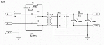
I am building the DoZ from ESP, and maybe have some difficulties in correctly understanding the suggested supply schematic. Here is the schematic:
If I connect my 30 - 0 - 30 toroid in the suggested way, I get about 60 V after the rectifier, and a short via the centre tap if produced, or am I misinterpreting anything?
So, normally I just would use one half of the toroid, with the centre tap connected to second AD rectifier pin, and the second half of the toroid not connected at all, is this right?
Of course, I could also use a 15 - 0 - 15 toroid, but right now I only have the 30 0 30 one...
I simply want to verify this before contacting R. Elliot himself...
Thanks for help,
Arndt
I am building the DoZ from ESP, and maybe have some difficulties in correctly understanding the suggested supply schematic. Here is the schematic:
An externally hosted image should be here but it was not working when we last tested it.
If I connect my 30 - 0 - 30 toroid in the suggested way, I get about 60 V after the rectifier, and a short via the centre tap if produced, or am I misinterpreting anything?
So, normally I just would use one half of the toroid, with the centre tap connected to second AD rectifier pin, and the second half of the toroid not connected at all, is this right?
Of course, I could also use a 15 - 0 - 15 toroid, but right now I only have the 30 0 30 one...
I simply want to verify this before contacting R. Elliot himself...
Thanks for help,
Arndt
Supply schematic is correct. With 30 0 30 transformer you will get about 42 V DC. The other secondary windings feeds the positive half wave and the other feeds the negative half.
I have never seen solution like this but if you have transfomer with two secondary windings you can use it this way to get one DC voltage. Normally you would use transformer which has only one secondary windings.
I have never seen solution like this but if you have transfomer with two secondary windings you can use it this way to get one DC voltage. Normally you would use transformer which has only one secondary windings.
But, like I said, it can't be correct. If I wire everything that way The fuse blows up instatly, and without fuse ... well, let's say that keeping it powered for more than 1 - 3 seconds would surely result into transformer meltdown...
If I just connect the two windings to the rectifier (without the caps, and no central tap connected) and measure DC voltage across the output of the rectifier I get about 57 V, or 60 V with caps connected. As soon as I connect the central tap to the "-" pin of the second cap a short is being produced, resulting in fuse blowing up (or the trasformer producing awful "crackling" noises 😱 )
And the trafo and rectifier are OK, they work flawlessly with my GainClone...
As it is, the schematic is wrong. A short-circuit exist between the center tap and the minus of the bridge, which will explode when the power will be switched on.
In my opinion, the minus of the bridge must be not connected. Only two diodes of the bridge are used, and the supply will produce approx 44 Vdc without load, and 36 Vdc at full load.
Regards, Pierre Lacombe.
In my opinion, the minus of the bridge must be not connected. Only two diodes of the bridge are used, and the supply will produce approx 44 Vdc without load, and 36 Vdc at full load.
Regards, Pierre Lacombe.
If you don't connect the negative to ground it'll work, or if you disconnect your center tap from ground. Good thing you had a fuse because otherwise you'd of probably blown some diodes in your bridge (I've done it before).
Very big oops!
 Arrrggghhhhh!
My apologies to all - the supply shown on the secure site is indeed wrong. The diagram will be updated tonight.
For some obscure reason, the original supply has been available for ages, but no-one pointed out the error (and I certainly didn't see it).
Again, my apologies for any inconvenience, and the new one should be available in a couple of hours.
Cheers, Rod
rode said:[BMy apologies to all [/B]
Mine too! I simulated the schematic without connecting the miinus pin of the bridge.
- Status
- Not open for further replies.
- Home
- Amplifiers
- Solid State
- DoZ power supply schematic wrong or unclear?
