My considerations on the fudge factor
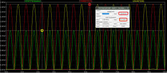
1. I considered to divide -V(OUT)*I(rSPEAKER) by 2 as both are AC RMS. Hence to get the RMS output power I divided it bot with (1.414 x 1.414)
2. Whereas I divided -V(N002)*I(V2) with only 1.414 as V(N002) has a static value.
As suggested, I did redraw the plots with plot from the -Ve rail added. For Symasym the ratio of output power to drawn power is 78.68% (202.19784/256.96604) but in my design other current overheads from the front-end, the VAS and the output stage which is version of CFB is (17.25 + 21 + 10 + 28 + 28 + 100 + 100 mA). So approximately 20W overhead on the rails to maintain the operating point along with the full AC drive @2 Ohms. Hence the efficiency drops to 59.88% (not only the output stage).
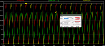