Your explanation certainly makes sense. Thanks!
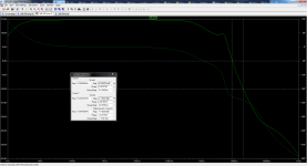
How do I write those parameters you mention: 500uS total run, saving after 100uS, and a timestep of 0.0015258uS. Should and how do I accommodate those values for other frequencies?
How do I write those parameters you mention: 500uS total run, saving after 100uS, and a timestep of 0.0015258uS. Should and how do I accommodate those values for other frequencies?
Like this?
.tran 0 500uS 100uS 0.0015258uS
How do I get to the last number and what does it mean?
.tran 0 500uS 100uS 0.0015258uS
How do I get to the last number and what does it mean?
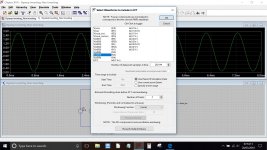
Getting the timestep right gives maximum possible precision in the FFT analysis. The timestep relates to the number of calculations that the simulation makes... if you get it to small then the sim can take ages to run, if it all. Get it to large and data will be missed as it is sampling to infrequently.
It is a value you can experiment and play around with, but the optimum value seems to be calculated as I outlined earlier by using the number of sample points you have selected (the 262144 in the case of LTXVII) in relation to the time the simulation runs for.
You will see how important this is if you do any FFT plots. The 262144 number is alterable in the dropdown on the FFT screen. Earlier versions used a lower number.
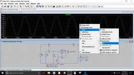
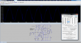
I don't run LTIV at all now but the method is the same. Run your simulation, right click the window displaying the trace and select <view> and <FFT>
Do you see 262144 or something else ? It is alterable via the selection arrows.
Do you see 262144 or something else ? It is alterable via the selection arrows.
Attachments
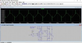
The spikes are caused by crossover distortion but remember you are looking 'inside the NFB loop' here. The output will look clean. If you increase the bias the spikes will lessen.
Here is a totally different amplifier that has a single ended input stage. No LTP here.
This shows the voltage drive on the collector of the first transistor stage that drives the VAS. The main amp output is clean. This is how feedback works. The only point of interest is the main output.
Here is a totally different amplifier that has a single ended input stage. No LTP here.
This shows the voltage drive on the collector of the first transistor stage that drives the VAS. The main amp output is clean. This is how feedback works. The only point of interest is the main output.
Attachments
This "spikes thing" also arised on another project I'm working on based on a Luxman amp.
In that case I could tame the spikes with some re-arrangement of passive parts in the driver section. THD went down too. No need to increase the bias.
But on another Luxman amp, with quite similar architecture, that trick didn't work. The only way to cure the spikes was increasing bias four times, which also increased watts on each output bipolar by the same rate.
So I have wondered if it was fine to leave the spikes in peace and don't mess around too much the original design, even on the first amp I mentioned.
But one thing is certain: taming the spikes improves THD.
I think you just have to accept they are a normal artefact of the way an amplifier with NFB works.
If the amp meets its published specification then there is little more you can do. Also many commercial amps are deliberately underbiased to both improve long term reliability (because customers often place things on them and cover them) and also that to run an amp at its optimum current means more expense is needed for heatsinking. Its always a compromise with mainstream commercial gear.
If the amp meets its published specification then there is little more you can do. Also many commercial amps are deliberately underbiased to both improve long term reliability (because customers often place things on them and cover them) and also that to run an amp at its optimum current means more expense is needed for heatsinking. Its always a compromise with mainstream commercial gear.
Very good point.
Now what can you say about frequency & phase simulation, Bode plots and amp stability?
Please look at the AC asc file I had uploaded, and use that as an example. You can sim it too on your LTSpice.
Cursor 1 is on the 0dB line. Cursor 2 is on the 180 degrees line.
What puzzles me are two things:
1) Why the degrees numbers I get do not correspond to the ones on the right vertical scale: 60 degrees and 180 degrees?
2) Why the cursor can not slide through the phase curve, as I have seen on other sims?
What can you say about stability of this amp?
Attachments
Look at the little dots at the right of the box. You have 'mag' or magnitude selected and that is read off from the left hand scale. If you select phase then the cursor will jump to show the new position for phase on the right hand scale.
The cursors should be movable to wherever you want them to be.
The cursors should be movable to wherever you want them to be.
Attachments
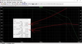
OK, the cursors jump to the phase curve.
How do I get the right phase degrees on the box?
You had them at 0 and 180 degrees tracking the mag. trace, if you look where the vertical cursor lines cross the dotted phase trace you'll see that the readings were correct. Once you move the cursors to track the phase trace it should be more obvious.
Voltage feedback amplifiers like these can oscillate and become unstable when the feedback loop is closed and the internal phase shifts are enough to start to turn the negative feedback into positive.
All amplifiers delay a signal by some amount (nothing ever happens instantaneously) and so as you look ever higher in frequency you will find some point where the signal shifts enough in phase that it causes problems.
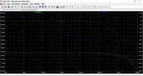
If you use the 'copy' function in LT you can duplicate a circuit on the same workspace. Here is Dougs amp as standard at the left and with the feedback replaced by a 1000GH inductor at the right.
I've attached the .asc but you will have to put your own models into it.
The inductor allows the DC conditions to remain correct but appears as open circuit to AC signals.
Also have a read at this from page 1.11 where it begins:
http://www.analog.com/media/en/training-seminars/design-handbooks/Basic-Linear-Design/Chapter1.pdf
Although they are referring to an opamp, our power amplifier is very similar... its like a power opamp.
The image shows Dougs amp under normal closed loop conditions (green) and open loop (blue)
All amplifiers delay a signal by some amount (nothing ever happens instantaneously) and so as you look ever higher in frequency you will find some point where the signal shifts enough in phase that it causes problems.
If you use the 'copy' function in LT you can duplicate a circuit on the same workspace. Here is Dougs amp as standard at the left and with the feedback replaced by a 1000GH inductor at the right.
I've attached the .asc but you will have to put your own models into it.
The inductor allows the DC conditions to remain correct but appears as open circuit to AC signals.
Also have a read at this from page 1.11 where it begins:
http://www.analog.com/media/en/training-seminars/design-handbooks/Basic-Linear-Design/Chapter1.pdf
Stability Criteria Feedback theory states that the closed-loop gain must intersect the open-loop gain at a rate of 6 dB/octave (single-pole response) for the system to be stable. If the response is 12 dB/octave (2 pole response) the op amp will oscillate. The easiest way to think of this is that each pole adds 90° of phase shift. Two poles then means 180°, and 180° of phase shift turns negative feedback into positive feedback, which means oscillations.
Although they are referring to an opamp, our power amplifier is very similar... its like a power opamp.
The image shows Dougs amp under normal closed loop conditions (green) and open loop (blue)
Attachments
What on the Bode plot will determine if the amp is stable?
What points on what curves I mean? Please use the Self amp as example.
I could open your asc file alright. Probably we have same parts models.
What points on what curves I mean? Please use the Self amp as example.
I could open your asc file alright. Probably we have same parts models.
One thing I learned since March is how to use another tool in LTSpice to simulate stabilization: Tian probe.
... and here you can find a dual Tian probe with parameter stepping:
2stageEF high performance class AB power amp / 200W8R / 400W4R
=> see first posts index for the direct link of
"Playing with LTSpice: Dual Tian probe and parameter stepping".
BR, Toni
2stageEF high performance class AB power amp / 200W8R / 400W4R
=> see first posts index for the direct link of
"Playing with LTSpice: Dual Tian probe and parameter stepping".
BR, Toni
- Status
- Not open for further replies.
- Home
- Amplifiers
- Solid State
- Douglas Self amp simulation