While browsing the bookstands yesterday I saw this in Elektor,
The 5532 OpAmplifier, part 1 - ELEKTOR.com | Electronics: Microcontrollers Embedded Audio Digital Analogue Test Measurement
All the specs are in the link. Doug mentioned this amp in his new book but it was a surprise to see a "real developed version"
300ma quiescent... so how much output is available in class A I wonder when each individual device is a class ab stage.
Wonder how it sounds... this could be an opamp tweakers ultimate challenge, never mind using different devices, how about "mix and match".
I'd love to know how it sounds compared to say Dougs blameless amp.
My first question about this is - is it designed to run from a regulated supply? The specifications for the rails (+/-18.3V) look especially tight if not. Next would be - how did he manage to degrade the slew rate for the 5532 which is typically 9V/uS? Given the relatively modest output power, I think a bridged version using 128 chips is going to be a reasonable upgrade.😀
Last edited:
I think Douglas Self started a quiet revolution with this seminal design. Seeing something like this from the "Blameless" creator caused a shock in my mind. Now, after one week or so, I'm realizing that Elektor made it available to the masses, for evaluation purposes.
As said above, this is a quiet revolution.
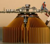
Imagine a small PCB having the same footprint as an Intel CPU. Using SMT quad-opamps. You then can apply an inexpensive CPU cooler. Imagine regulated switched-mode power supplies, kind of laptop power supplies. Imagine a bridged amp using a single 36V regulated switched-mode power supply. Imagine a 1ppm THD figure. Could it be we just entred the 1ppm Blameless gridAmp era ? More about this here : http://www.diyaudio.com/forums/chip-amps/174405-1ppm-gridamp.html#post2318498
As said above, this is a quiet revolution.
Imagine a small PCB having the same footprint as an Intel CPU. Using SMT quad-opamps. You then can apply an inexpensive CPU cooler. Imagine regulated switched-mode power supplies, kind of laptop power supplies. Imagine a bridged amp using a single 36V regulated switched-mode power supply. Imagine a 1ppm THD figure. Could it be we just entred the 1ppm Blameless gridAmp era ? More about this here : http://www.diyaudio.com/forums/chip-amps/174405-1ppm-gridamp.html#post2318498
I saw something like this before:
HeadWize - Project: A Precision Preamplifier-Power Amplifier System with Natural Crossfeed Processing by Jan Meier
so there *is* prior art ...
HeadWize - Project: A Precision Preamplifier-Power Amplifier System with Natural Crossfeed Processing by Jan Meier
so there *is* prior art ...
Thanks steph_tsf
I did a forum search but it didn't throw that one up of yours 🙂
I'll have a read.
I did a forum search but it didn't throw that one up of yours 🙂
I'll have a read.
. Seeing something like this from the "Blameless" creator
Beg to differ...
The "blameless" topology, that is, a LIN with an enhanced Vas
did exist well before Self popularized it...
"blameless" is not a topology.
It is a philosophy.
Design and assemble the amplifier properly and the distortion becomes so low that one cannot blame the amplifier for what one hears.
It's that philosophy, that draws criticism of D. Self's designs/writings from many.
It is a philosophy.
Design and assemble the amplifier properly and the distortion becomes so low that one cannot blame the amplifier for what one hears.
It's that philosophy, that draws criticism of D. Self's designs/writings from many.
Yet, his own "blameless" has an awful design when it comesIt is a philosophy.
Design and assemble the amplifier properly and the distortion becomes so low that one cannot blame the amplifier for what one hears.
It's that philosophy, that draws criticism of D. Self's designs/writings from many.
to the VAS and LTP respective CCS...
Yet, his own "blameless" has an awful design when it comes
to the VAS and LTP respective CCS...
Changing compensation scheme from simple Miller to Edmond's TMC would have much bigger impact on performances than changing CC sources.
Any chance we can keep this to the original topic... multiple paralled opamps as a power amplifier... thanks 🙂
My first question about this is - is it designed to run from a regulated supply?
The answer to this is yes, there's a circuit for a power supply in the .pdf article.
I wouldn't put too much reliance in the slew rate figure, the article may not have been very well proof-read, a little thing like that can easily slip through.
I'm delighted with the concept itself, it's novel and unconventional, it always pleases me when someone departs from the expected, and this is certainly not something I expected, or I would have tried it myself.
It's tempting to try building one, if there weren't plenty of amps around here already I'd be giving it a go. In fact it's likely I'll try some variation on this at some stage.
w
Mooly, did you see the other thread about this topic?
http://www.diyaudio.com/forums/chip-amps/174405-1ppm-gridamp.html
http://www.diyaudio.com/forums/chip-amps/174405-1ppm-gridamp.html
The slew rate puzzled me too... must have another gander at the circuit details.
This is one of those projects "where you just know you want too"... very intriguing.
The cost of using other opamps could be prohibitive though, 5532's are around £0.27 inc VAT for 50+ other devices around the £2 to £3 mark in similar quantities.
This is one of those projects "where you just know you want too"... very intriguing.
The cost of using other opamps could be prohibitive though, 5532's are around £0.27 inc VAT for 50+ other devices around the £2 to £3 mark in similar quantities.
Mooly, did you see the other thread about this topic?
http://www.diyaudio.com/forums/chip-amps/174405-1ppm-gridamp.html
I did... eventually
thanks
Get a better op amp? apply heat sink, use multiloop topology...
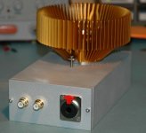
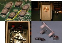
6x TPA6120 dual op amps, rated 400 mA each op amp - parallel pairs biased against each other for Class A push-pull output (a little over 200 mA Class A bias for the headphone amp)
this is sized as a headphone amp so the outputs are cascaded for higher drive V (600 Ohm cans or the insanely low sensitivity AKG K1000)
TPA has exposed Cu power pad meant to be soldered to board for several W dissipation, by soldering "belly up" I contact them to the Cu slug of a pc cooler - running ~ 30 W quiescent total without fan
re arranging the I,V by flat paralleling you could get 2.4A, 15 V peak each channel for ~ 14 Wrms into 8 Ohms Class AB stereo
all up, both channels paralleled as a monoblock the shown components, heatsink should drive down to ~3 Ohms
...
Imagine a small PCB having the same footprint as an Intel CPU. Using SMT quad-opamps. You then can apply an inexpensive CPU cooler...
Imagine a 1 ppm THD figure...
6x TPA6120 dual op amps, rated 400 mA each op amp - parallel pairs biased against each other for Class A push-pull output (a little over 200 mA Class A bias for the headphone amp)
this is sized as a headphone amp so the outputs are cascaded for higher drive V (600 Ohm cans or the insanely low sensitivity AKG K1000)
TPA has exposed Cu power pad meant to be soldered to board for several W dissipation, by soldering "belly up" I contact them to the Cu slug of a pc cooler - running ~ 30 W quiescent total without fan
re arranging the I,V by flat paralleling you could get 2.4A, 15 V peak each channel for ~ 14 Wrms into 8 Ohms Class AB stereo
all up, both channels paralleled as a monoblock the shown components, heatsink should drive down to ~3 Ohms
Attachments
Last edited:
The answer to this is yes, there's a circuit for a power supply in the .pdf article.
I wouldn't put too much reliance in the slew rate figure, the article may not have been very well proof-read, a little thing like that can easily slip through.
I'm delighted with the concept itself, it's novel and unconventional, it always pleases me when someone departs from the expected, and this is certainly not something I expected, or I would have tried it myself.
It's tempting to try building one, if there weren't plenty of amps around here already I'd be giving it a go. In fact it's likely I'll try some variation on this at some stage.
w
I will be bringing the Elektor prototype to BAF. Hear for yourself!
As to proofreading, this unit has been extensively tested in the Elektor lab. Those specs are real-world measurements.
jan didden
I will be bringing the Elektor prototype to BAF. Hear for yourself!
jan didden
Have you had chance to listen to it at home ? or at least in known surroundings where you could get a true impression of it's performance.
Changing compensation scheme from simple Miller to Edmond's TMC would have much bigger impact on performances than changing CC sources.
True that TMC greatly improve the thing, but then , the CCS
are to be improved one way or another..
sorry for the OT....
Last edited:
Have you had chance to listen to it at home ? or at least in known surroundings where you could get a true impression of it's performance.
I had a short casual listening in the Elektor lab, but will do more testing before coming to BAF.
But it is interesting to hear what sounds like a good poweramp knowing that its just a bunch of opamps ;-)
jan didden
- Home
- Amplifiers
- Chip Amps
- Doug Selfs NE5532 Power Amp. Thoughts anyone !