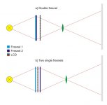
I've made a small illustration of my understanding on the subject (see the attached image).
The first setup shows the use of double fresnel lens (used in OHP). The double fresnel acts as a double convex lens. The light that hits the LCD is not parallel, that's why the edges of the projected image are often dimmer than the center.
The second setup uses two fresnels that act as two separate plano convex lenses. Between these two lenses the light should be parallel. So, if we place the LCD in between, we will improve the projected image, making the brightness more even.
Just want to know if I'm right. What do you think?
Attachments
Many, many designs call for this. I don't know of anyone actually trying it. My assumption is that the rings need to match up perfectly, and I would think that's tough to do.
...my little 12 inch panel should make it reasonably easy to find frezi's that will "fit" the screen size.
zardoz
zardoz
You are exactly right.
I'm using the second config BTW.... 2 single fresnels with the LCD in between. (I dont know of anyone else doing this here)
I'm using the second config BTW.... 2 single fresnels with the LCD in between. (I dont know of anyone else doing this here)
jcbklyny said:You are exactly right.
I'm using the second config BTW.... 2 single fresnels with the LCD in between. (I dont know of anyone else doing this here)
What fresnels did you use (size, manufacturer, url, etc.)? Did you align the two fresnels to match their "ring" structure as Lifter points our attention to? What is the distance between two fresnels in your setup?
Lifter said:Many, many designs call for this. I don't know of anyone actually trying it. My assumption is that the rings need to match up perfectly, and I would think that's tough to do.
I think the moire effect will be present if the two fresnels are too close to each other (as in first setup), e.g. if you try to make a diy double fresnel instead of building the OHP one.
But something tells me that if you place the LCD between two fresnels, giving some space (1"...2") between each plane, the moire would not be the case. You will have just to align two lenses by center axis as you would do with normal lenses. Hope jcbklyny will shed some light on it.
Again, remembering what neededandwanted said about optics that go after the LCD (and carry the projected image), the second fresnel (the dark blue one on the scheme) on the second setup should be of a better quality than OHP-like plastic lenses we've stuck to.
Anyone knows a good e-store for quality fresnels or big plano-convex lenses 15" in diameter?
Anyone knows a good e-store for quality fresnels or big plano-convex lenses 15" in diameter?
afan said:
Anyone knows a good e-store for quality fresnels or big plano-convex lenses 15" in diameter?
Hehe. That's the million dollar question.
Your second drawing is the preferred by for exactly the reason you point out. The lines go straight thru the panel.
As a side benefit, you can play with the spacing a lot. Parallel light isn't spreading out, so you can put some room in there. The moire patterns are the result of interference between the pixels and the fresnel, not between the two fresnels. Look at a brand-new OHP. The two fresnels are practically touching faces in most cases.
Remember that the parallel light needs to hit the bumpy side of the fresnel lenses (on both sides.) That is to say, light that is diverging can go in or out of the flat sides. (A few are made backwards, but VERY few.)
Those of you that already have your head wrapped around this concept can skip the rest of this post.
Basically, it is pretending to be a plano convex lens that is all surface and no middle (since ALL refraction takes place on the surface where two materials meet--the middle is full of straight lines).
The flat side is perfectly emulating the plano side of a 'real' lens. The convex side, however has a bunch of "illegal" surface, between the convex parts.
This illegal part is all of the tiny ringed surfaces between the angled tops. The parts that are perpendicular to the flat (other) side. This is the non-lens section surface on the bumpy side.
If you were to imagine Manhattan as all tall buildings of different heights and the buildings were all pushed up against each other (losing all of the streets and sidewalks) and all of the buldings had angled roofs. The lens surface would be all of the angled tops of the buildings. The illegal surface would be all of the sides of the buildings.
If non-parallel light goes into the bumpy side of a fresnel, it falls on the sides of the lens rings. That light will either reflect back, or go inside the lens and bounce around. When you hold up a fresnel with a light bulb shining nearby, the reflection off of the illegal surfaces is the sparkle you see. It makes a pattern a bit like light bouncing off of an old LP record.
Light coming in from within the focal cone on the flat side should never show these artifacts.
You CAN special order these to be made backwards. In that case all of the ridges are leaning (for the Manhattan analogy, imagine all of the buildings leaning inward towards the center somewhat so that only the rooftops get any sunlight, and none of the sides of the buildings get any). You can also get concave fresnels. Again, you are not likely to see any of these by accident.
For a standard fresnel, just keep the ridgy side only receiving at, or projecting parallel rays. The flat sides should get all of the non-parallel light. The sides of the ridges shouldn't have light try to go in or out of them. The sides of the ridges should never "see" your lamp, mirror, your panel on any lens.
For those of you that totally already knew this: I warned you not to read it. For those of you that don't understand what the hell I think I'm talking about and are now more confused than ever: let me know. I'll re-write it, taking out 1000 words, and adding a picture.
You'll need two high quality fresnels... and just because a fresnel is plastic doesnt mean it's crap!... Most optical grade plastic fresnels are better then any glass fresnel you can buy... period.
I built my setup in a frame structure... meaning the entire inner frame pulls away from the outter casing. By doing this you can mount the fresnels perfectly even with one another... You should use fresnels with the same number of grooves per inch. Mixing them up will give you ring patterns on screen.
By placing the LCD between 2 fresnels as a few of you have guessed, Your able to pass more light evenly through the LCD. Spacing IS easier too... and you DO have a lot of room to play with.
...And lastly... make sure you mount the collector fresnel at the right focal length to your light source!!! If not you will never be able to light up the entire panel evenly no matter what!
If you use a condenser lens mounted above your reflector use that as the starting point. Not the floor of your projector!
If you use a condenser lens mounted above your reflector use that as the starting point. Not the floor of your projector!
URLs, please. And, again, what exact fresnels did you use?jcbklyny said:BTW large optical grade fresnels are expensive!!! Not hard to find 🙂
I've came across this site with rather quality plastic lenses (not so expensive though): http://www.fresneltech.com/visible.html, see their PDF brochure. They have 12" fresnels. Did anyone use them?
LCD sandwich
Has anyone tried cutting apart the Elmo fresnels and putting the top one on top of the LCD?
How will this affect our image quality? Edge brightness?
Can you leave an inch of space for fan cooling of the LCD?
I'll try it on my setup if we agree it'll work....
Has anyone tried cutting apart the Elmo fresnels and putting the top one on top of the LCD?
How will this affect our image quality? Edge brightness?
Can you leave an inch of space for fan cooling of the LCD?
I'll try it on my setup if we agree it'll work....
proto5
well jeez I never thought of that! I have an old Elmo HP14 here that I'll rip the Fresi out of and take a look at this idea.
zardoz
well jeez I never thought of that! I have an old Elmo HP14 here that I'll rip the Fresi out of and take a look at this idea.
zardoz
Here is another store with big quality fresnels:
http://www.edmundoptics.com/IOD/DisplayProduct.cfm?Productid=2040
http://www.edmundoptics.com/IOD/DisplayProduct.cfm?Productid=2040
chop-chop
Well......Since no one else was game......
I just finished seperating my Elmo fresnels.
Bandsaw on the corners and Dremel on edges.
Focal lengths are verified as:
LOWER=9.5"
UPPER=12.5"
Will get back online after testing the LCD sandwich idea.
Well......Since no one else was game......
I just finished seperating my Elmo fresnels.
Bandsaw on the corners and Dremel on edges.
Focal lengths are verified as:
LOWER=9.5"
UPPER=12.5"
Will get back online after testing the LCD sandwich idea.
WOO-HOO!!!!!!!Success!!!!
Holy Crap.......
I have seen the light....and it's name is split fresnels!!!
Split Elmo fresnels- put one on top of LCD (about 1"gap for cooling)
This is the answer guys- PERFECT edge to edge brightness
PERFECT Focus
95% picture usage
And finally a SQUARE PICTURE!!!!!!
Why didn't we do this before???
Get out the tools, guys.
Will do screenshots after dark tonite & post here.
-Proto5
NEC1545
Elmo SD305
9A62 component-VGA adapter
- Status
- Not open for further replies.
- Home
- General Interest
- Everything Else
- The Moving Image
- DIY Projectors
- Double fresnels vs. two single ones