When doing Class A we may be restricted to not as high Wattage.
After all we will not use many of those Watt.
With normal speakers the sound can be loud enough at 1 Watt output.
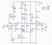
I have designed to have 16 Watt output.
For this I select to bias 1.20 Ampere through output.
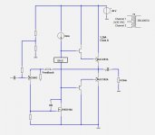
My amplifier does not use many transistors.
Only those who can give a very good result.
As you can see from the simplified diagram
I use single power supply, so one transformer feeds two channels.
One 30 VAC winding per channel gives 40 VDC for each.
This of course means I use output capacitor at half the supply.
After all we will not use many of those Watt.
With normal speakers the sound can be loud enough at 1 Watt output.
I have designed to have 16 Watt output.
For this I select to bias 1.20 Ampere through output.
My amplifier does not use many transistors.
Only those who can give a very good result.
As you can see from the simplified diagram
I use single power supply, so one transformer feeds two channels.
One 30 VAC winding per channel gives 40 VDC for each.
This of course means I use output capacitor at half the supply.
Attachments
Long ago I designed and built a very similar amp, all bipolar however, and my recollection is that it performed pretty well sonically and in terms of measurements I was able to do at the time - I found the simplicity appealing. Mine was also deliberately designed to have relatively low OLG and greater than 20kHz open loop bandwidth. Subjectively I liked it better than an otherwise similar LTP based design - I did not have the means to look at the harmonic spectra of the amplifier, but I suspect this played a role. (I was also surprised by my preference at the time)
You need a big heatsink for each channel.
But not too big.
It is only 50 Watt heat for each channel.
This is not much for a Class A amplifier.
But not too big.
It is only 50 Watt heat for each channel.
This is not much for a Class A amplifier.
Looks like something based on JLH's 10W design Lineup. I recently designed and built a class A amp (the 'sx-Amp'). It's fully blanched however. You can read about it only website.
Your design looks very interesting.
Your design looks very interesting.

If you like to build Class A ...
... then this circuit is for you.
Just get yourself a transformer 2x30 VAC.
Should be 300 to 400 VA.
The transistors are easy to find.
MJL3281A and MJL1302A are used in many good amplifiers.
The MOSFET, ZVN3310A is a great little TO92 transistor.
It is a lovely sunday here in Sweden.
Clouds cover the sky. All is white and -10 C degrees cold.
The swedish girls I do not have to tell you about.
They are often blond and beautiful 🙂
I have wanted to move to Sweden for a while. I also like the look of Lund University? I thinks it's in Sweden!
You might as well use a LTP at the front end. What made you not do this?
It's an antiquated topology that is modified for class A operation. LTP offers advantages but subjectively this old school topology (emitter feedback) is easier to stabilise. (I don't know why.) Also this topology subjectively offers good audio performance, even though technically it is not as accurate as LTP (which is actually an error amplifier). Technically this emitter feedback topology introduces errors but this can be mitigated as well (the low value feedback network resistors help with this objective).
There's really nothing wrong with it in my opinion. For DIY I think it's easier to sort out. DC performance is not an issue and closely matched parts are not required. Its simplicity is a virtue.
Hi Guys
The dome topology has nothing to do with the JLH 10W, rather more to do with Lin. The heart of the JLH-10 is the use of the driver/CVAS as a splitter driving both output devices directly. This contributed to ghastly distortion while allowing a low parts count.
Both use a single-BJT input stage, which in modern terms forms a CFP wit the voltage amplifier and could also be described as a "current feedback" amp - see Rod Elliot's similar design, but biased class-B.
Input stages like this are easy to stabilise and compensate because the signal path is a tight loop - not convoluted by a third member as with a diff-amp input. The downside of this approach is that the collector current of the input devices must flow through the feedback resistor. This drives the R value lower to maintain reasonable DC setting of the output, in turn driving the shunt R value for the FB loop down. The design has come full circle with the CFB/CFA rage.
Have fun
Kevin O'Connor
- Status
- Not open for further replies.
- Home
- Amplifiers
- Solid State
- Dome - a 16 Watt push-pull Class A amplifier