Hi Guys,
Busy trying to put this EAR 864 back to original spec. It has a long history of problems and is about to get its 3rd set of output transformers! I've never seen one before and can find only one circuit diagram at the back of the (from Hfe) owners manual - which seems to be a slightly different version.
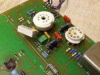
After spending many hours on the net looking at 864 pictures, I think I have a fairly good idea of what should and shouldn't be there. But the 3 series resistor cap arrangement in the attached image, this seems to be unique to this unit. They occupy R3 and R103 positions.
PCB is a 2799-4 revision. Whoever worked on it before removed just about every component. I even found resistor pairs transposed, a pair of 3k3 (R2) where 6k8 (R7) should go, and vice versa. The 3 resistor in series // with the cap works out to less than half the 330k specified in the circuit diagram. Possibly the transposed parts created new problems and then the race was on to 'mod' the hell out of it.
I have some doubt though because the combo is fairly neatly soldered, much better than a lot of the other work. Has anyone seen this arrangement in an 864 before.
If you do have an 864, I'd be really gratefull for any well lit focused images you might care to post. If I can confirm all resistor values (ideally from an unmolested unit) I'm prepared to draw out a schematic of this version.
Oh, the large 330E resistor R15, bottom centre of image, on the PCB it is marked 1K5, but this might be because the board is multifunctional? The phono board has a very similar supply and on this unit, there indeed appears a 1K5. I think I saw a 330E on at least one online image, but it hard to make out colours from photos sometimes.
Thanks!
Busy trying to put this EAR 864 back to original spec. It has a long history of problems and is about to get its 3rd set of output transformers! I've never seen one before and can find only one circuit diagram at the back of the (from Hfe) owners manual - which seems to be a slightly different version.
After spending many hours on the net looking at 864 pictures, I think I have a fairly good idea of what should and shouldn't be there. But the 3 series resistor cap arrangement in the attached image, this seems to be unique to this unit. They occupy R3 and R103 positions.
PCB is a 2799-4 revision. Whoever worked on it before removed just about every component. I even found resistor pairs transposed, a pair of 3k3 (R2) where 6k8 (R7) should go, and vice versa. The 3 resistor in series // with the cap works out to less than half the 330k specified in the circuit diagram. Possibly the transposed parts created new problems and then the race was on to 'mod' the hell out of it.
I have some doubt though because the combo is fairly neatly soldered, much better than a lot of the other work. Has anyone seen this arrangement in an 864 before.
If you do have an 864, I'd be really gratefull for any well lit focused images you might care to post. If I can confirm all resistor values (ideally from an unmolested unit) I'm prepared to draw out a schematic of this version.
Oh, the large 330E resistor R15, bottom centre of image, on the PCB it is marked 1K5, but this might be because the board is multifunctional? The phono board has a very similar supply and on this unit, there indeed appears a 1K5. I think I saw a 330E on at least one online image, but it hard to make out colours from photos sometimes.
Thanks!
Attachments
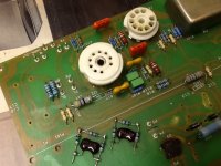
Here is another image showing the 'mods' removed and replaced with the 330K specified in the schematic. I've also swapped over the transposed 3K3 / 6K8 resistors to agree with the diagram. Incidentally, the mustard coloured capacitors are not present in some designs. They are 10pF devices.
Attachments
- Status
- Not open for further replies.