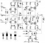
I found this scanned schematic in the net, I got interested and would like to construct it (for the reason of low power and parts availability), i was hoping my 200w 8ohm speakers won't blow

Seriously does this schematic looks promising?
 All of your comments, recommendations is very much appreciated
Seriously does this schematic looks promising?
Attachments
http://www.diyaudio.com/forums/solid-state/174783-crescendo-millennium-offset-problem.html
This will help in case of problem..
The schematic is the same , apart from the output devices since
this is an evolution of the one you are interested in..
Of course, both are from elektor mag.
This will help in case of problem..
The schematic is the same , apart from the output devices since
this is an evolution of the one you are interested in..
Of course, both are from elektor mag.
Last edited:
Isn't this is the Elektor (Giesberts) Hexfet amp published in the december 1993 edition? There's also another higher powered version with IGBT's published in sept 1995. I have built the IGBT version 12 yrs ago, and experienced some stability problems (oscillations).
You might find a lot of information in this thread :
http://www.diyaudio.com/forums/solid-state/112426-hexfet-amp-please-help-me-fix.html
You might find a lot of information in this thread :
http://www.diyaudio.com/forums/solid-state/112426-hexfet-amp-please-help-me-fix.html
Hi,
this uses a FET CFP output stage.
It could have oscillation problems.
The BD139/140 used for VAS are attrocious for VAS duty. They are good for drivers in the next stage.
However, I notice only a little stability compensation added elsewhere.
The use of the high Cob VAS transistors may be a way of incorporating Cdom without fitting/buying extra components.
got another one!
That scared me dennismati thank you for bringing that up...........anyway
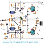
I got another one from the net (attached) both had the same circuitry and the same power requirements and was designed by swagatam innovasion from brighthub site. I overlooked the first schematic it looks to me that the resistor values are of the 5 band type. They are hard to find here, but of course putting a no. of resistors in series will also do but that would be impractical for it will only take a lot of pcb space.
This one had the average resistors you can always find, but it has missing parts (i have to wait for the authors feedback yet) perhaps it was overlooked when posted in the site. Values for R18, Voltage trimmers P1& P2, Transistors T9-11 were missing from the parts listing (below).
Parts List
All resistors are ¼ watt CFR unless otherwise specified.
R1 = 1M, R2, 27 = 47K, R3, 20, 21 = 470Ω, R10, 11, 12, 13, 28, 17 = 1K, R6, 7, 8, 9 = 56Ω, R29, 30 = 330K, R14, 15 = 270Ω, R26 = 4K7, R16, 19 = 100Ω, R22, 23 = 0.25/2W, WIREWOUND R24 = 1Ω, R25 = 10Ω, C1 = 2µ2, C2 = 1 nF, C3, 4 = 10 Pf, C5 = 47 nF, C6, C7 = 100µ/50V, C8, 9 = 10,000/63v, D1, 2 = LED RED, D3, 6 = 1N4148, D4, 5 = 12V/400mW Zener, Power Supply Diodes = 6 Amp. 300V T1 = MAT 02, T2 =MAT 03, T3 = BC 560C, T4 = BC550C, T5 = BF 470, T6 = BF469, T7 = 2SK 135, T8 = 2SJ50
In this case, I was hoping you can help me out guys here and figure what was the missing values!!!
Will these values do ?– T10=2SK170 (its a FET right?), T11=BC550C, R18=1k, P2=500ohms. Also can a couple of BC550 & BC560 can replace MAT02/03 for the differential amp? Two in one transistor packaging is much harder to find.
Honestly this is my first attempt to build a mosfet having built bi-polars so far, until I got a copy of Anthony Holtons 2SK1530/2SJ201 1994 Mosfet design, I never built it, it was a huge amp with -/+70v rail & a 500VA power requirement. However, my colleague built it and made it to work. Me, so far was looking for a medium power at the least.
All feedbacks is very much welcome or you can e-mail me at cjames_lco@yahoo.com
That scared me dennismati
thank you for bringing that up...........anywayI got another one from the net (attached) both had the same circuitry and the same power requirements and was designed by swagatam innovasion from brighthub site. I overlooked the first schematic it looks to me that the resistor values are of the 5 band type. They are hard to find here, but of course putting a no. of resistors in series will also do but that would be impractical for it will only take a lot of pcb space.
This one had the average resistors you can always find, but it has missing parts (i have to wait for the authors feedback yet
) perhaps it was overlooked when posted in the site. Values for R18, Voltage trimmers P1& P2, Transistors T9-11 were missing from the parts listing (below). Parts List
All resistors are ¼ watt CFR unless otherwise specified.
R1 = 1M, R2, 27 = 47K, R3, 20, 21 = 470Ω, R10, 11, 12, 13, 28, 17 = 1K, R6, 7, 8, 9 = 56Ω, R29, 30 = 330K, R14, 15 = 270Ω, R26 = 4K7, R16, 19 = 100Ω, R22, 23 = 0.25/2W, WIREWOUND R24 = 1Ω, R25 = 10Ω, C1 = 2µ2, C2 = 1 nF, C3, 4 = 10 Pf, C5 = 47 nF, C6, C7 = 100µ/50V, C8, 9 = 10,000/63v, D1, 2 = LED RED, D3, 6 = 1N4148, D4, 5 = 12V/400mW Zener, Power Supply Diodes = 6 Amp. 300V T1 = MAT 02, T2 =MAT 03, T3 = BC 560C, T4 = BC550C, T5 = BF 470, T6 = BF469, T7 = 2SK 135, T8 = 2SJ50
In this case, I was hoping you can help me out guys here and figure what was the missing values!!!
Will these values do ?– T10=2SK170 (its a FET right?), T11=BC550C, R18=1k, P2=500ohms. Also can a couple of BC550 & BC560 can replace MAT02/03 for the differential amp? Two in one transistor packaging is much harder to find.
Honestly this is my first attempt to build a mosfet having built bi-polars so far, until I got a copy of Anthony Holtons 2SK1530/2SJ201 1994 Mosfet design, I never built it, it was a huge amp with -/+70v rail & a 500VA power requirement. However, my colleague built it and made it to work. Me, so far was looking for a medium power at the least.
All feedbacks is very much welcome or you can e-mail me at cjames_lco@yahoo.com
Attachments
The first amp makes a good oscillator. Avoid it.
The second amp's schematic has several errors too.
Quasi's NMOS amps are good designs - Quasi's DIY Audio Site
The second amp's schematic has several errors too.
Quasi's NMOS amps are good designs - Quasi's DIY Audio Site
Last edited:
You could always build mine which uses Lateral FET'. It's all here but you would have to make your own boards. Super stable design due to the topology used.
http://www.diyaudio.com/forums/solid-state/119151-my-mosfet-amplifier-designed-music.html
Alex MM did a great looking PCB.
http://www.diyaudio.com/forums/solid-state/119151-my-mosfet-amplifier-designed-music.html
Alex MM did a great looking PCB.
Attachments
is post1 in that link the recommended schematic? or do we search for later versions?
Circuit is correct, however 10 ohm non inductive resistor should be added across output inductor.
I would advise anyone contemplating this design to read all the thread to gain an insight into it's design and operation. It's very forgiving (in the best possible sense) for a DIY constructor and should be totally stable even with less than ideal layout.
that was a relief!
thank you guys for giving me something to think about Now I guess I had to re-consider the matter before constructing (surely don't want to spend something that would be disappointing) I will surely consider your options & thanks for the schematics that's a lot of help!
thank you guys for giving me something to think about
Now I guess I had to re-consider the matter before constructing (surely don't want to spend something that would be disappointing) I will surely consider your options & thanks for the schematics that's a lot of help!thank you guys for giving me something to think about
Better build the Quasi's design which i've tried,they are good even using IRFP240 which is abundant in PH especially RAON and very cheap. I've also tried other Vfets from junked SMPS and they work fine for the ckts.
I was reconsidering the one from Mooly, coz 2n5401/5551 abound in the shop I've working on and of course in the local stores
The quasi design looks very neat though and that was an option too
thanks to jaycee
Any TL071/81 or half of TL072/82.
- Status
- This old topic is closed. If you want to reopen this topic, contact a moderator using the "Report Post" button.
- Home
- Amplifiers
- Solid State
- does this mosfet schematic looks promising?