HiHi homemade,
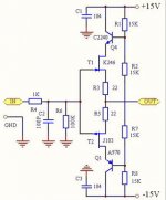
that is cascoded complementary buffer, well known/used and nice performing circuit. Usually, it's made with 2sk170/2sj74.
2sk246/2sj103 are a bit different jfets (less transconductance).
Try it and tell us how does it sound
Is this buffer can work on Ucc=+/-9V or need something changed?
What needs to change the schematic to its input resistance is 1Mohm?
thank you
Hi
Is this buffer can work on Ucc=+/-9V or need something changed?
Remove R1, R2, R7, R8, Q4 & Q8, fit links on the PCB in the Q4 & Q8 collector/emitter position.
Make R6 1M.What needs to change the schematic to its input resistance is 1Mohm?
Take a look at the input of the F4 amplifier buffer in the Pass Labs forum, also have a look at the DCB1 buffer as an alternative.
Last edited:
Remove R1, R2, R7, R8, Q4 & Q8, fit links on the PCB in the Q4 & Q8 collector/emitter position.
What needs to change the schematic to its input resistance is 1Mohm?
Make R6 1M.
Forgot to mention, remove C2, otherwise you will have a bandwith of 1.6KHz.
Strange cascode.
In Juma's circuit, the base voltage of each common base bipolars is half way between the output and the rail.
In Homemade's circuit, R2 and R7 are in series and not connected to the output.
Using this connection, a fet associated with its bipolar do make not cascode at all.
In Juma's circuit, the base voltage of each common base bipolars is half way between the output and the rail.
In Homemade's circuit, R2 and R7 are in series and not connected to the output.
Using this connection, a fet associated with its bipolar do make not cascode at all.
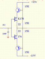
Post 1 is a true cascode. Post 3 results in a constant Vds for the fets, sort of like a bootstrap. I think for a common drain circuit (source follower), constant Vds may be more advantageous.🙂
Neither of the circuits in posts 1 and 3 are cascodes: both are partially bootstrapped complementary followers. The post 3 circuit is not really a buffer as, because of the input filter, it will have a low input impedance except at fairly low frequencies.
thats ok for me,more sound from dac and of course cleaner amplification
but will the potentiometer work after it ?
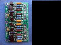
-- i mean the pcb in post 2,i bought one on ebay and thought that the buffer will make that separation between circuits to make it possible to use pots
but will the potentiometer work after it ?
-- i mean the pcb in post 2,i bought one on ebay and thought that the buffer will make that separation between circuits to make it possible to use pots
They are both nice circuits.
But usual is the problem to get those JFET from any shop.
That is why I would suggest a Diamond Buffer,
which only use nice common BJT bipolar transistors.
Will save the problem of getting devices.
But usual is the problem to get those JFET from any shop.
That is why I would suggest a Diamond Buffer,
which only use nice common BJT bipolar transistors.
Will save the problem of getting devices.
i allready got pcbs and j-fets and,i would like to see a schematic of that diamond buffer..
please respond to my question - will the pot work without cutting highs at low volume
please respond to my question - will the pot work without cutting highs at low volume
I see no reason why a pot should not work. The details, as always, would depend on issues such as cable capacitance.
If any highs are to be cut this will be at highish volume (-6dB), as is normal for pots.
If any highs are to be cut this will be at highish volume (-6dB), as is normal for pots.
Last edited:
- Status
- Not open for further replies.
- Home
- Amplifiers
- Solid State
- Does this FET buffer circuit look familiar?