Does this actually work, or is it a joke.
ice video 20210929 185234 - YouTube
If it works as intended, what will the power then be with a good 75 Vdc power supply be in 8 and 4 ohms?
ice video 20210929 185234 - YouTube
If it works as intended, what will the power then be with a good 75 Vdc power supply be in 8 and 4 ohms?
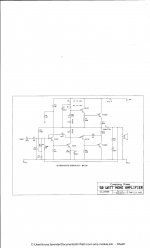
Well it seems to be six paralleled 10A PNP switching power transistors connected in the wrong polarity without emitter-spreaders and no DC-blocking for the speaker, so I'd simply avoid!
[ Ah, on a second closer look the amp _when running_ has the power polarity opposite to that in the build instructions(!)... That makes sense
since that gives a self-biased class-A circuit. ]
[ Ah, on a second closer look the amp _when running_ has the power polarity opposite to that in the build instructions(!)... That makes sense
since that gives a self-biased class-A circuit. ]
Last edited:
I knowed where I failed building this now......
Schoolboy error I know....
I didn't use yellow cable for the output

Try putting that heatsink in a cab ..... or a car
Schoolboy error I know....
I didn't use yellow cable for the output
Try putting that heatsink in a cab ..... or a car
Well it seems to be six paralleled 10A PNP switching power transistors connected in the wrong polarity without emitter-spreaders and no DC-blocking for the speaker, so I'd simply avoid!
[ Ah, on a second closer look the amp _when running_ has the power polarity opposite to that in the build instructions(!)... That makes sense
since that gives a self-biased class-A circuit. ]
Is the capacitor on the input not a DC blocker?
How does the principle sound if you wear hifi glasses?
And again, how much will such a construction approximately deliver in 8 ohms with 75 vdc
I could do something similar with 2sc5200, just to try
Last edited:
I knowed where I failed building this now......
Schoolboy error I know....
I didn't use yellow cable for the output
Try putting that heatsink in a cab ..... or a car
I have a huge heatsink, but i dont know the circuit.
But i cab "see" that if i use a 75 vdc powersupply, then there will be alot heat from the transistors 😀
Well, what does "intended" mean? No specs.
One transistor (or parallelled) devices don't usually offer low distortion by themselves.
There is no current sharing resistors in the emitters - never a good idea.
The speaker acts as the load, so is biased in one direction - not a good idea.
There are other circuits out there with low component counts which may work far better - try Nelson Pass's site, or one of Suzyj's circuits.
Yes, but it doesn't block DC from the speaker though, so its being pushed assymetrically - the choke is an attempt to alleviate this I think.Is the capacitor on the input not a DC blocker?

Mark T -not sure what the choke is there for. It will limit the frequency response but little else. It is not even specc'd.
Running from 12V would only need one of those transistors I suspect. (Not checked the datasheet of the 2SB688).
With 6 devices you would be better splitting them into 3+3 in push pull, perhaps in a version of the JLH class A.
(Must be a joke or some demo of a single tranny stage as an amplifier. Not hifi.)
It looks like yet another "hey guys - I got sound from these surplus parts!" type video. It can't be serious - even the very brief sound sample was suspect and certainly, the heatsink would struggle with more than one transistor. I think it's a "me too" video, meant to leave an impression of the poster's video making skills rather than the content. To me, that is one dumb-a** monophonic amplifier.
Perhaps the coil is just what you see - a surplus ferrite power supply inductor substituted for what should be an air or iron-cored audio crossover type. You could also conclude that without some kind of lowpass filtering, the sound output must have been awful.
Perhaps the coil is just what you see - a surplus ferrite power supply inductor substituted for what should be an air or iron-cored audio crossover type. You could also conclude that without some kind of lowpass filtering, the sound output must have been awful.
Class A single transistor amplifier. A constant current flows through the speaker's voice coil. The choke would make sense as a load, but not in series with the speaker. The inductance should be much larger. The choke must have a magnetic gap against saturation of the magnetic circuit with direct current.

Last edited:

If I recall correctly Clive Sinclair published a crude circuit as in your post #11, Old DIY.
However, the OP's linked video at least positioned the bias resistor connected to the collector which gave a modicum of negative feedback. But the speaker still gets biased one way.
Your second circuit shows what might have been the purpose of the toroidal inductor, in the "joke" circuit but to be of any use it would have had to have been in the region of 50mH, not the 50uH or such that it probably was. The speaker would at least have had some mitigation of DC current flow.
Neither circuit you posted shows any sensible control of the current in the output tranny. And most power transformers are not suitable as they need an air gap so as not to become magnetically saturated by the DC flow. Which is also a problem even if the toroid in the video was supposed to be in parallel with the speaker instead of in series.
A well designed transformer and half decent circuit may have been worthwhile. But decent audio transformers are even more expensive than they used to be.
I wonder ... if you are prepared to run even more static current perhaps a bleed in the primary in the opposite direction to the secondary current might offset the worst of the DC magnetic biasing ....
Last edited:
It looks like yet another "hey guys - I got sound from these surplus parts!" type video. It can't be serious - even the very brief sound sample was suspect and certainly, the heatsink would struggle with more than one transistor. I think it's a "me too" video, meant to leave an impression of the poster's video making skills rather than the content. To me, that is one dumb-a** monophonic amplifier.
Perhaps the coil is just what you see - a surplus ferrite power supply inductor substituted for what should be an air or iron-cored audio crossover type. You could also conclude that without some kind of lowpass filtering, the sound output must have been awful.
I apologize for making this thread.
I'm making sure it does not happen again.
I jump on class D which can be bought for cheap money and in hifi quality
Depends on what you mean by "work". Ya, it makes a bit of sound, but we are talking maybe 1 Watt of audio using 1000W of power transistors, plus there is DC current in the speaker ... It's just a very bad class-A amplifier.
Does this actually work....
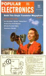
It is a gross variation on a 1956 plan. It does not need all those transistors. It heats-up and decenters the speaker pretty bad, even at idle. The choke is almost useless; it is certainly not working like the MOFO in the PASS forum section or OldDIY's #14 here.
Yes, the bias resistor and coupling cap have been replaced by a Carbon Microphone, a now obscure part. IIRC performance was so bad that the next year (when ordinary people could afford *two* transistors) an improved plan was published.
Attachments
Last edited:
- Home
- Amplifiers
- Solid State
- Does this actually work ?